Billig
Done: YES!! Click here to see it’s first benchy!
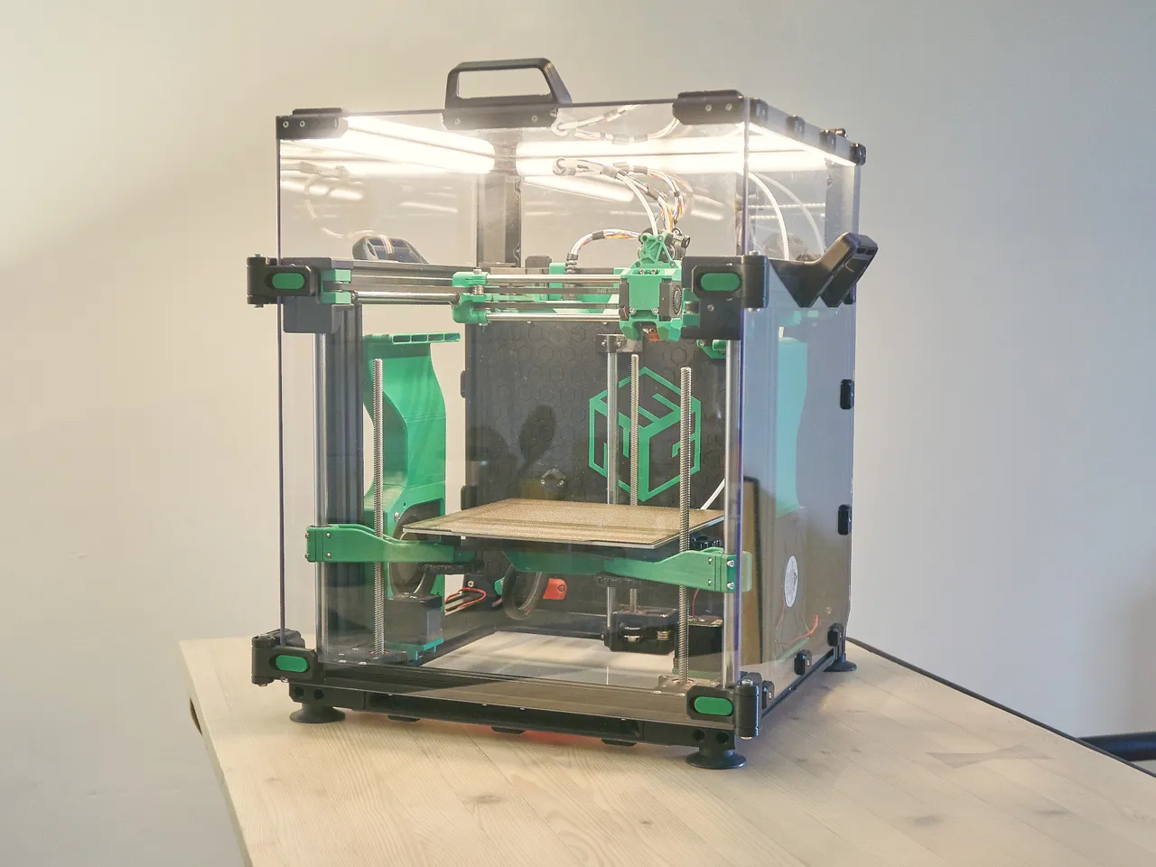
Result: ~500$ 440x230x260mm 3D printer
Author: @playlogo
Repository: https://github.com/playlogo/billig
Total hours so far: - lost count
Bom: Google sheets
CAD: Onshape
About the printer:
- 440x230x200mm printing volume
- 940x410x465mm frame
- Reuses a lot of parts from two “broken” Anycubic Kobra 2 Neos
- Direct drive extruder & dual 5020 part cooling
- Completely enclosed electronics
- Build-in ABL
- With a rpi zero & Klipper-Ready
- ~$500 (including the two broken printers)
Phase 3: Building
July 16th
Create a NeRF and a super fancy marketing video for it :D
July 14th-15th
Improved the config, added Z-tilt adjust, pressure advance, leveled the bed (it was kinda lopsided) and probed (many) bed-mesh(s).
Here’s my favorite one: Over 1.5mm difference from one side to the other
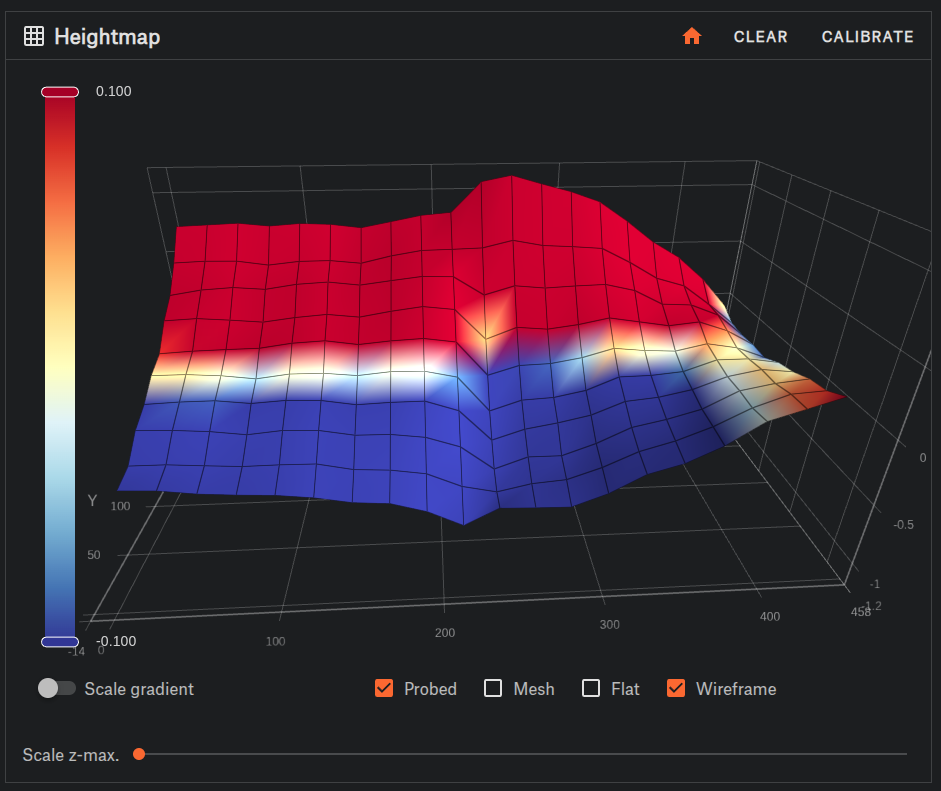
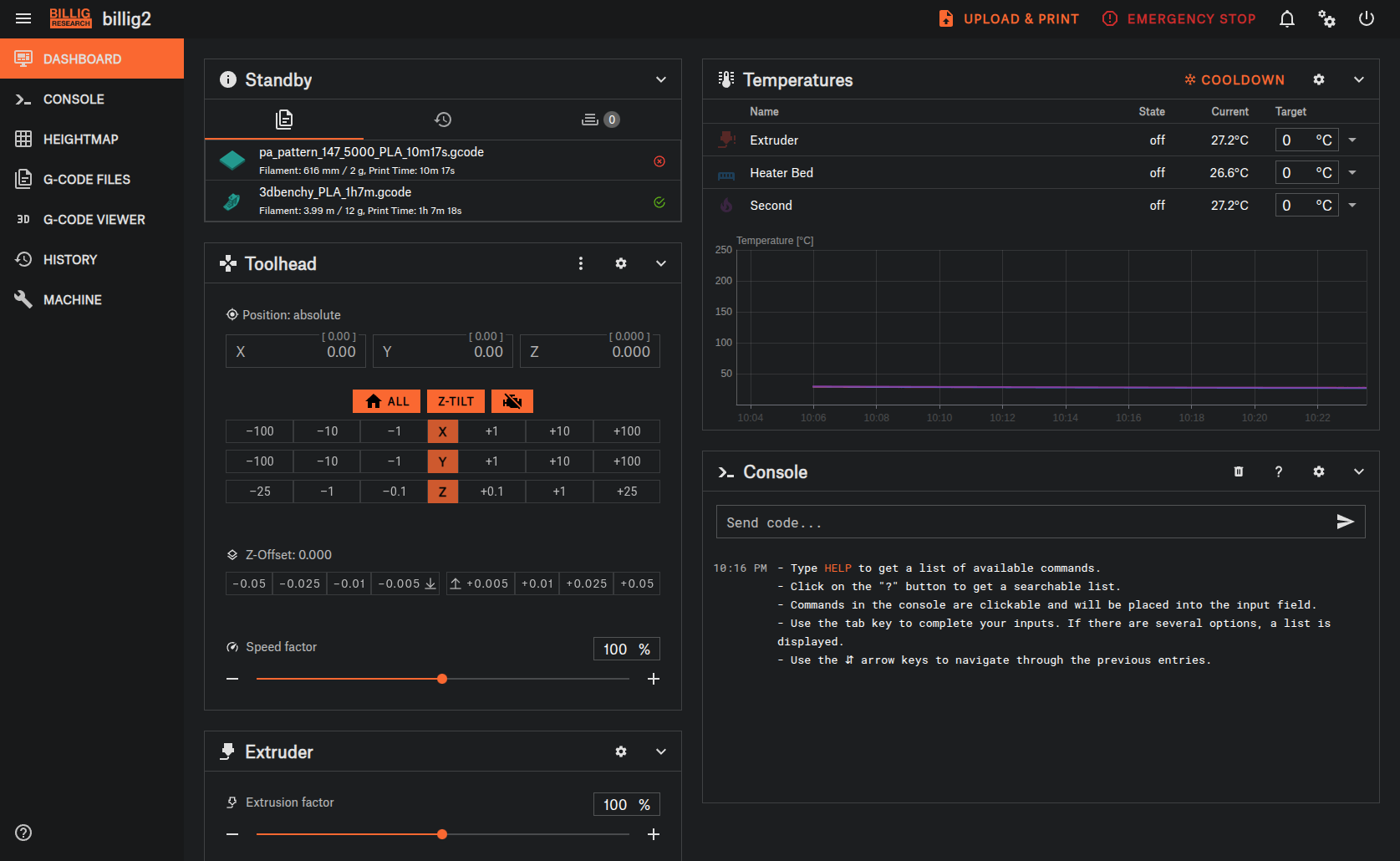
(Also I really really like the build-in PrusaBillig-Research theme in Mainsail!!)
July 13th
More klipper configuration and wiring fixes.
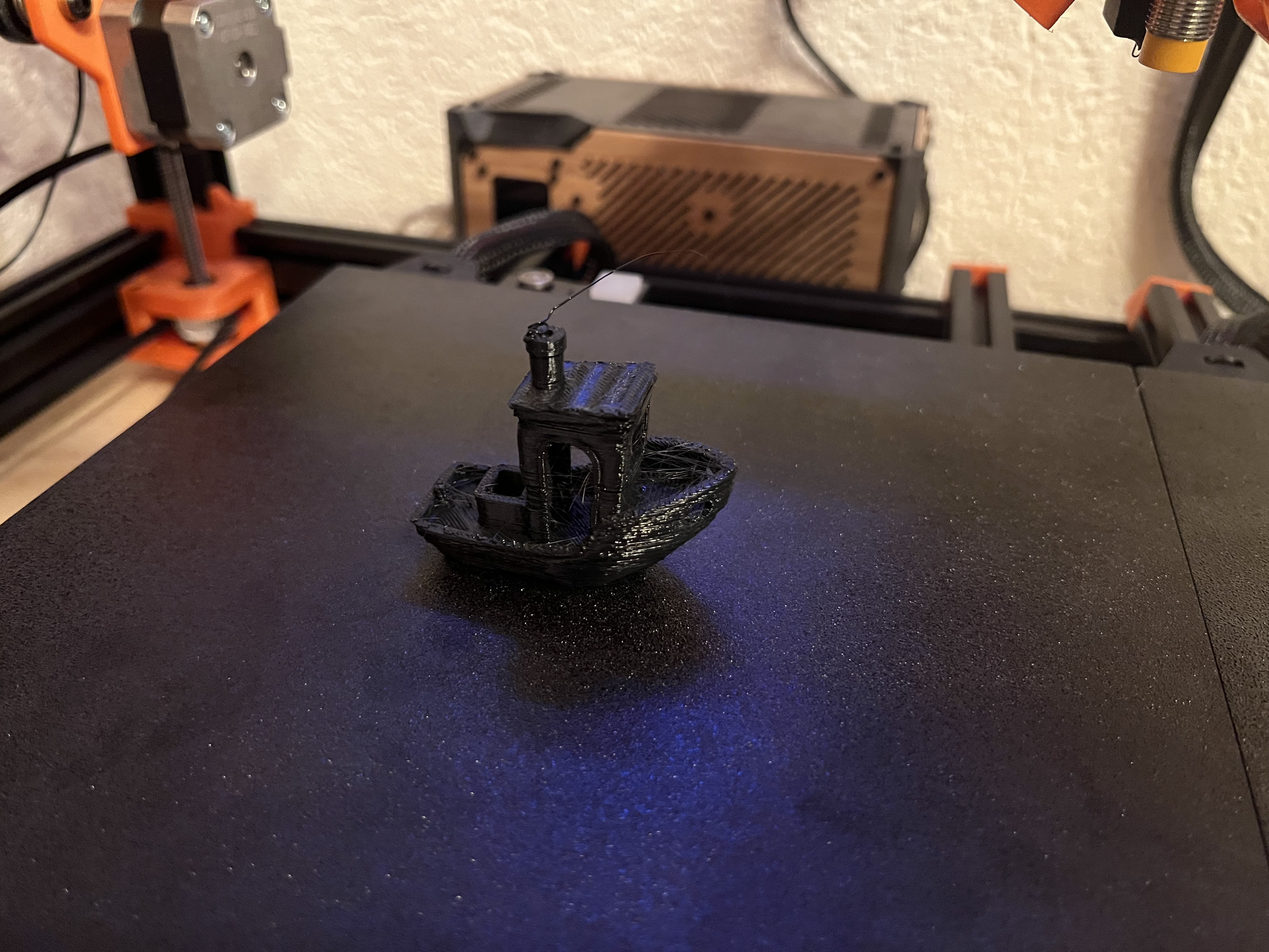
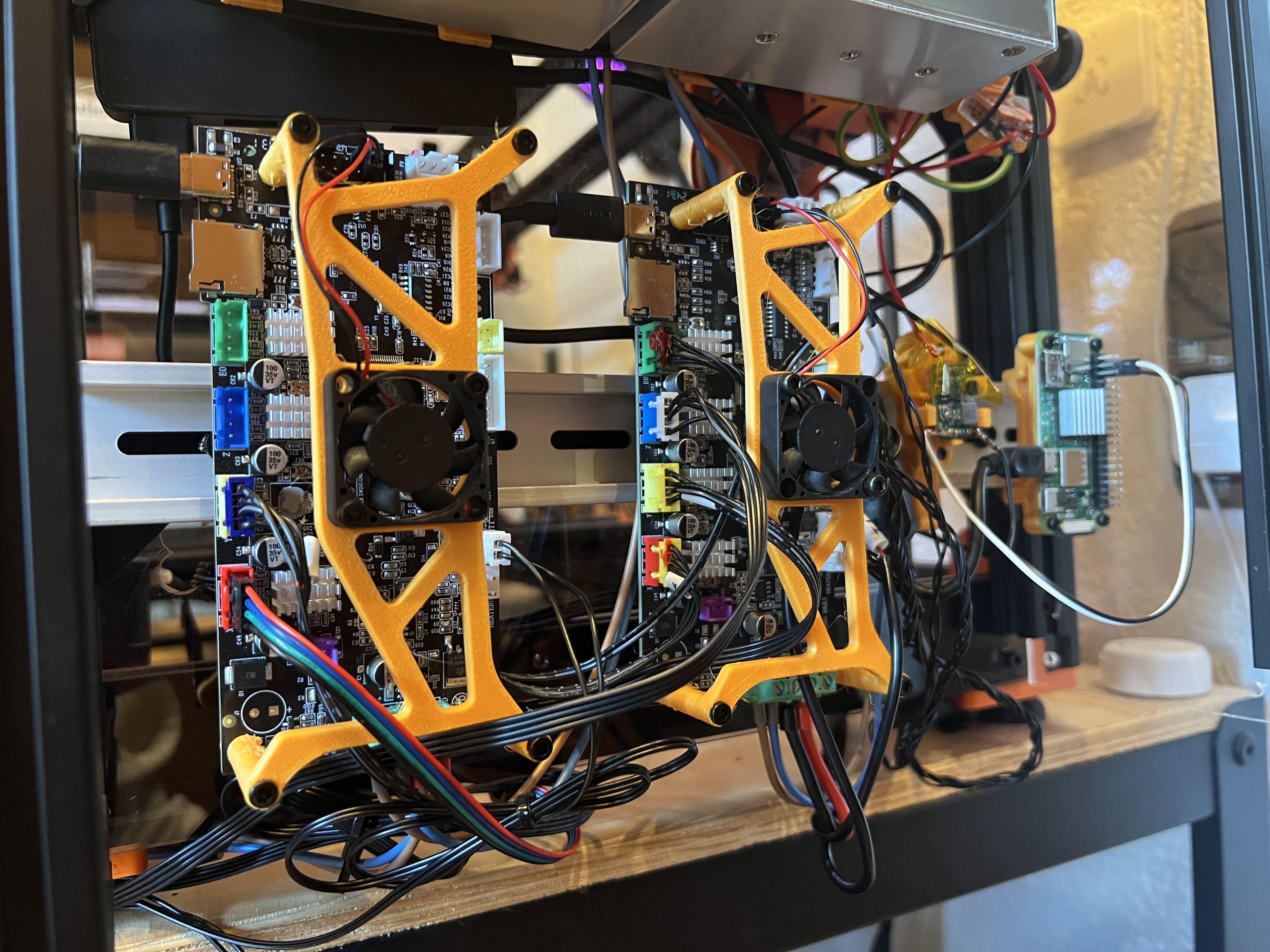
Toward the evening (or midnight, depending on how you define that) I got it to print it’s first bench!
I’m super proud of it, just look at it. No layer shifting (only minor extrusion issues and some stringing since the filament is super old)!!!
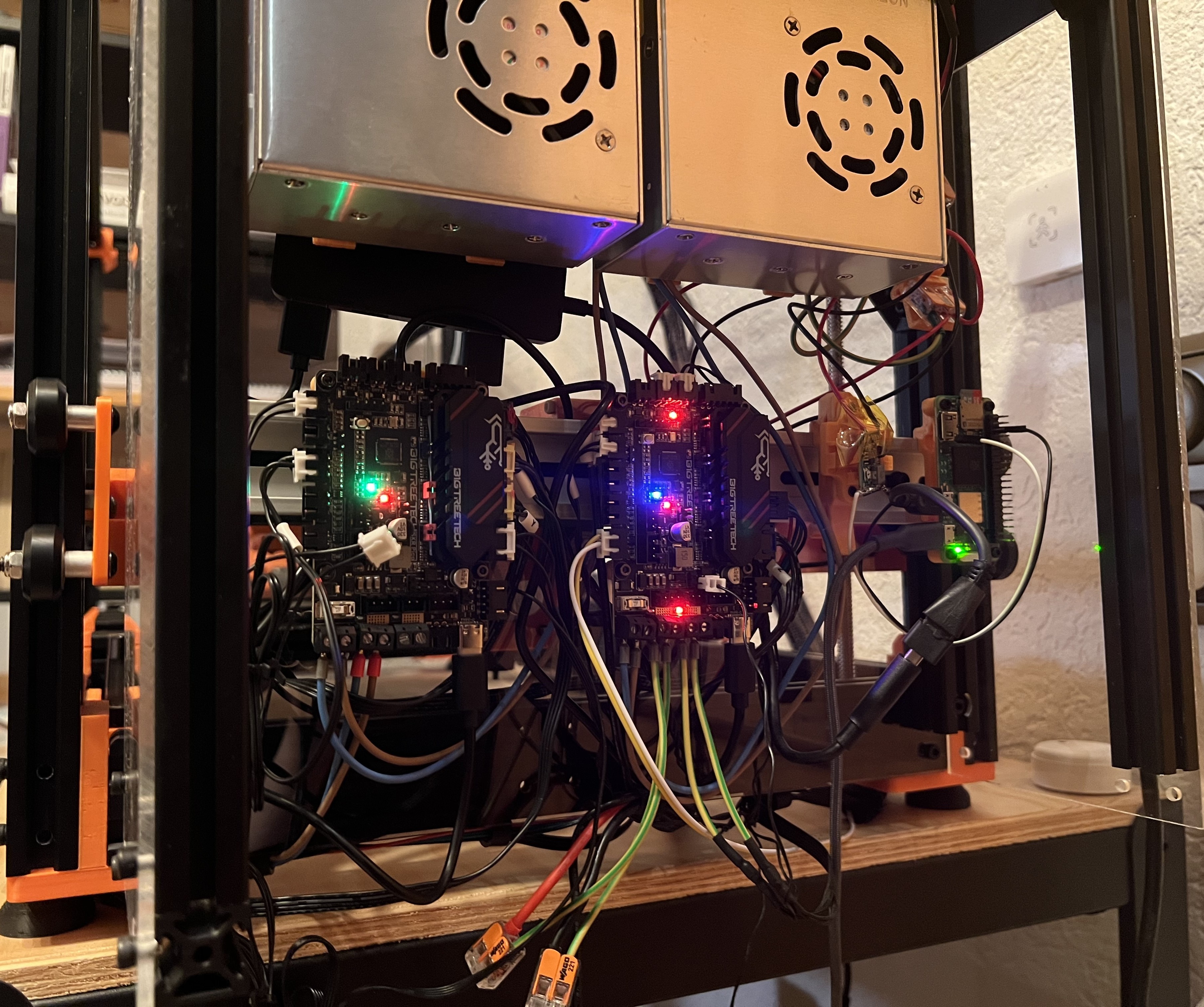
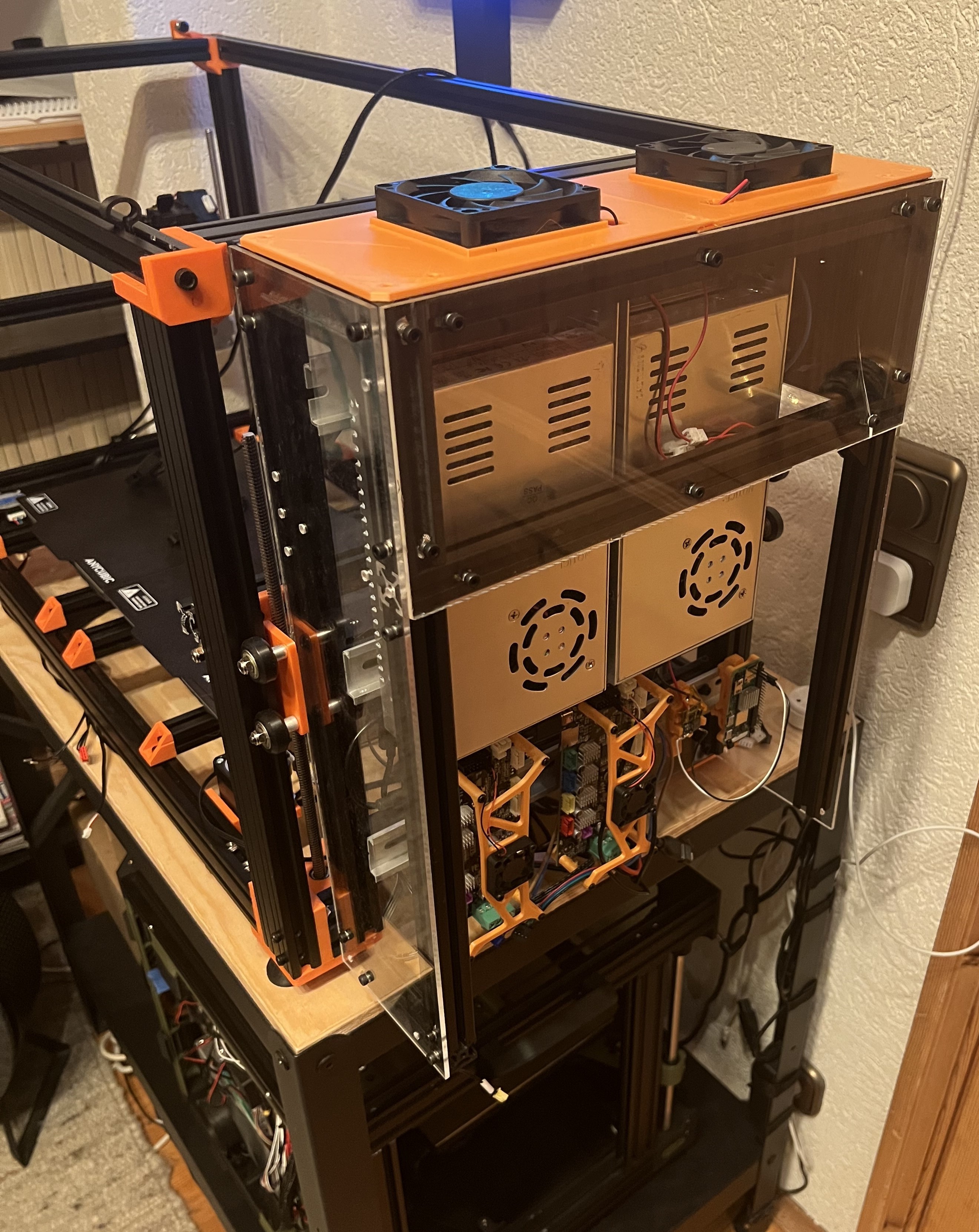
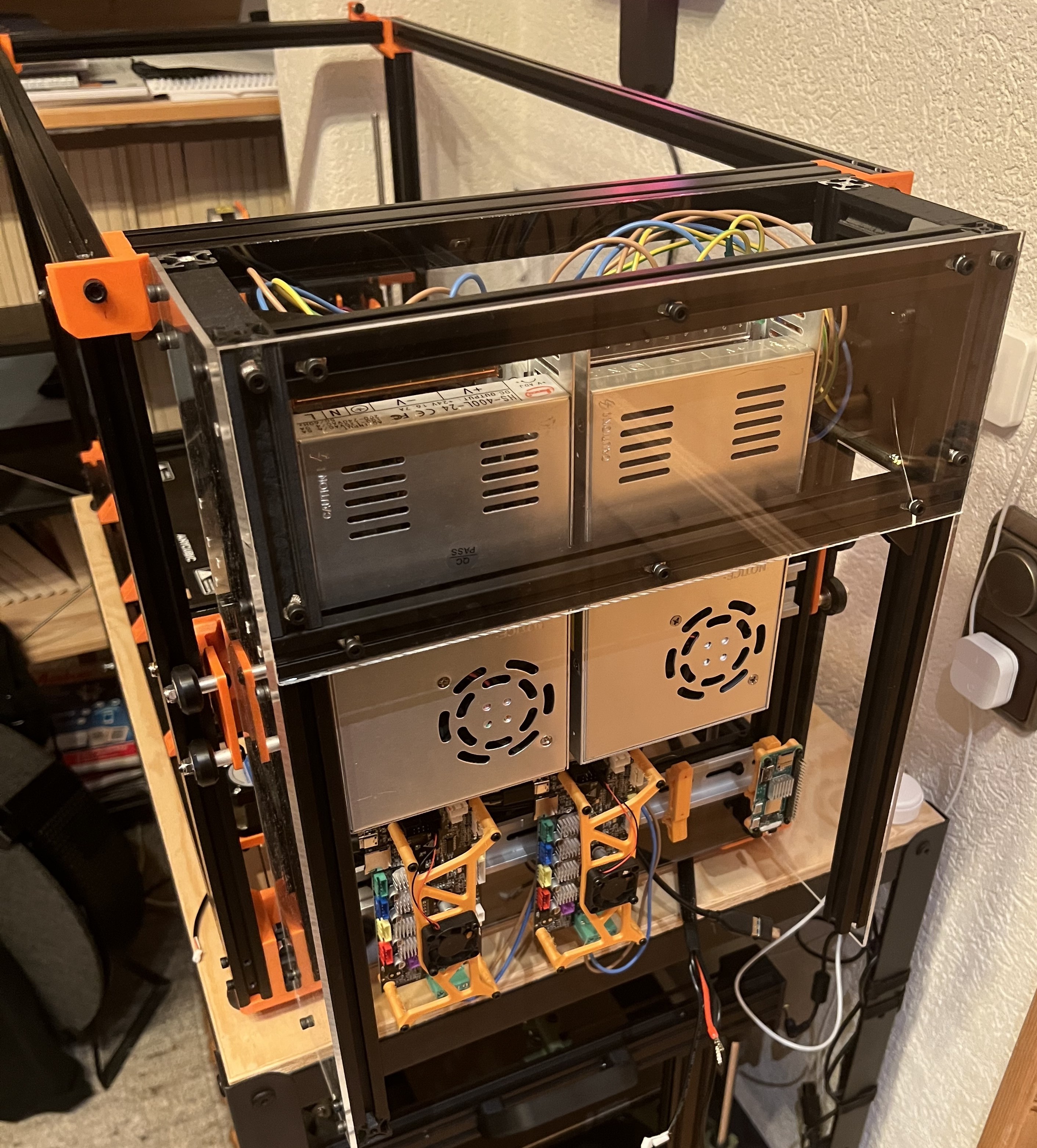
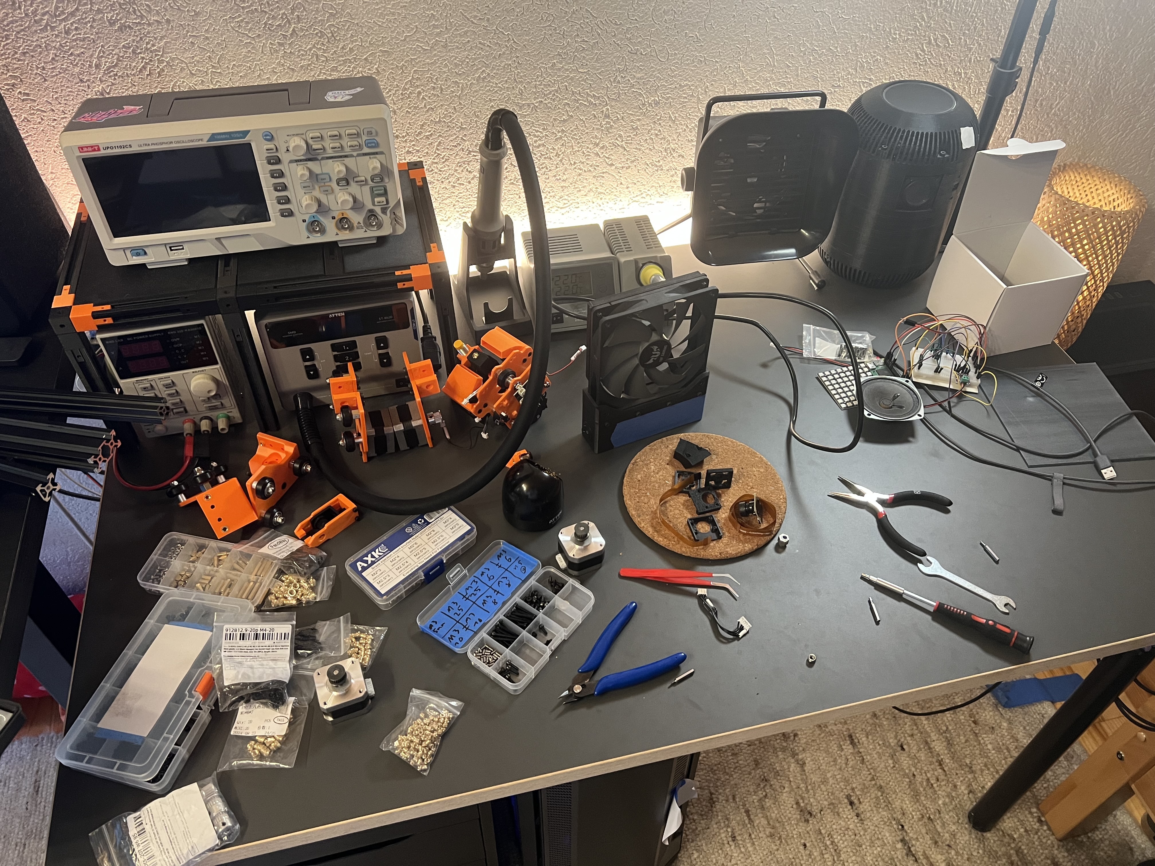
And the electronics look so cool!
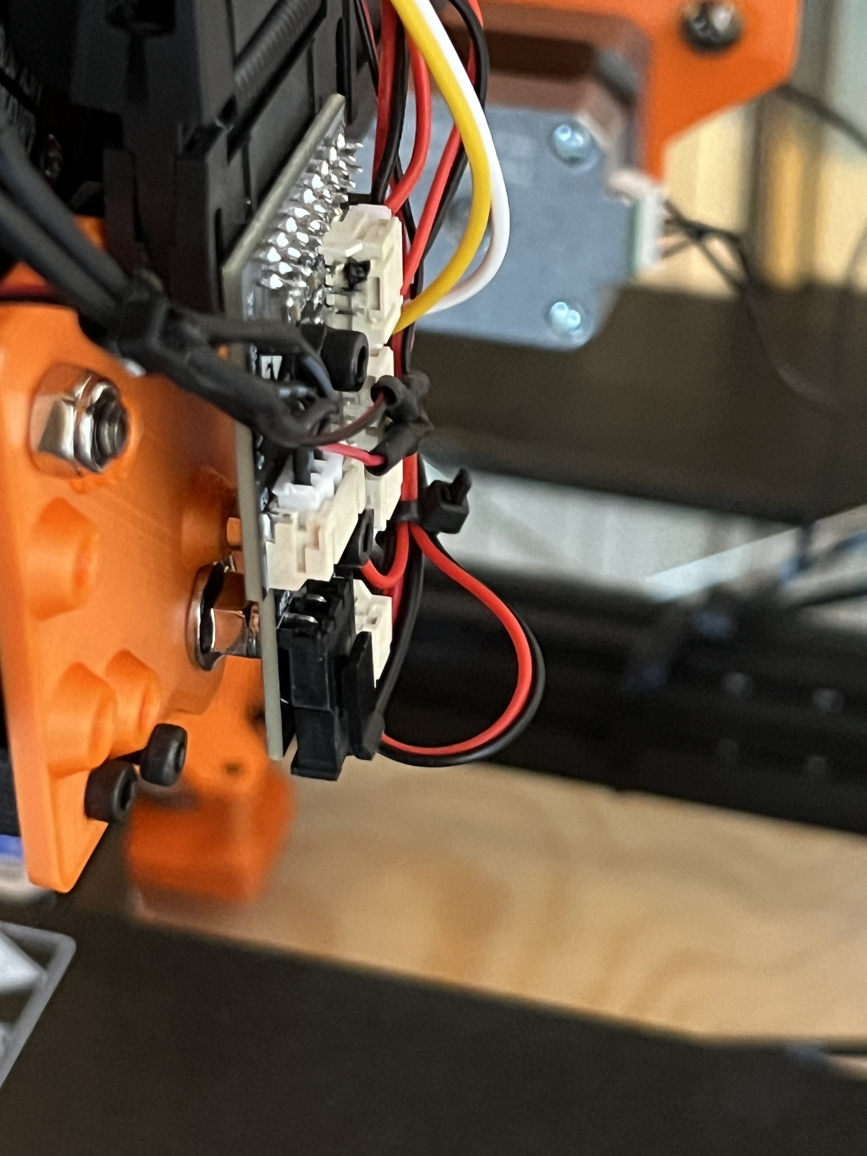
While trying to debug the Z-probe I manged to release the magic smoke of one of the toolhead breakout boards I reused from the defective printers.
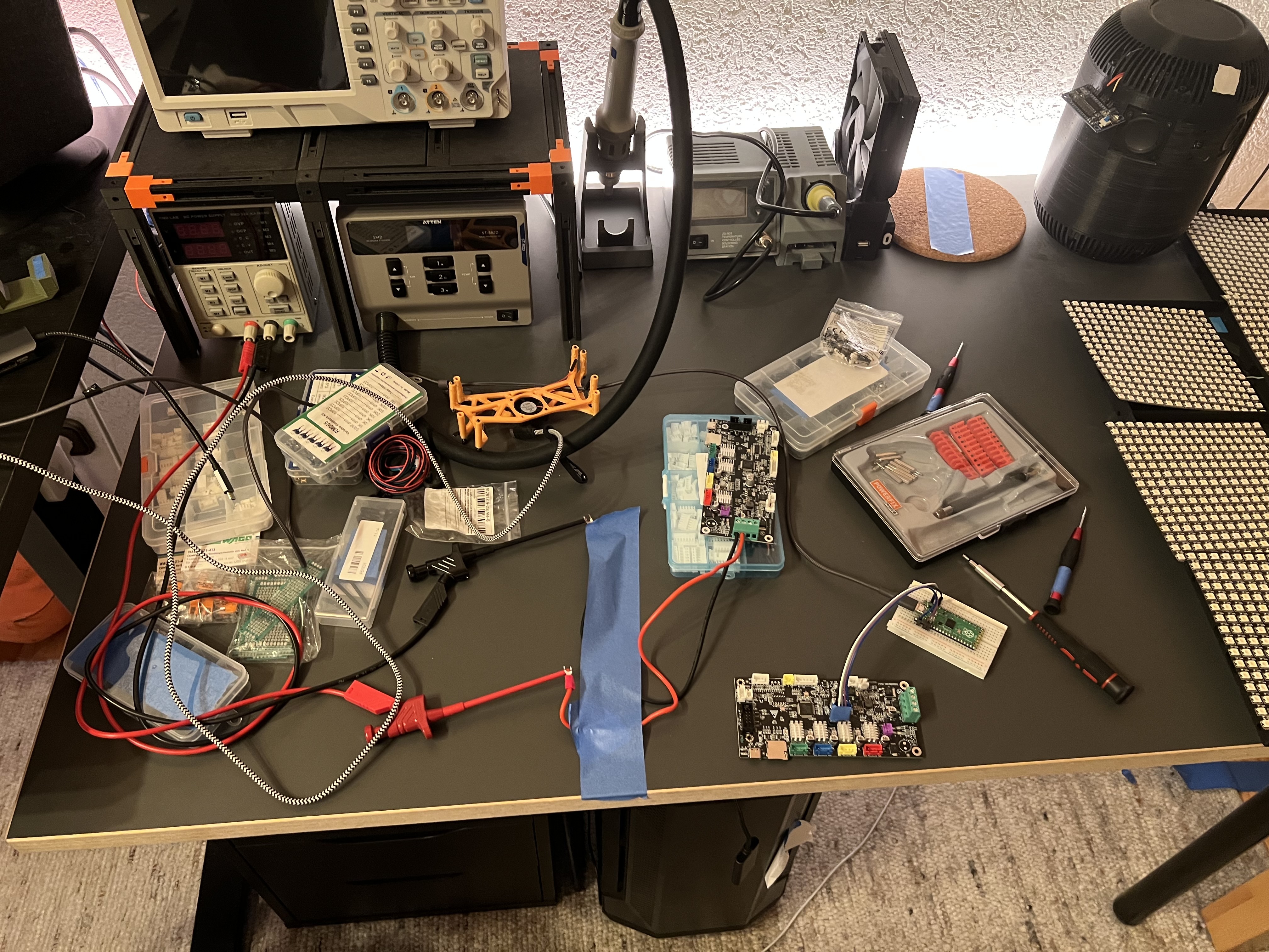
July 12th
Wired up the new SKR picos, flashed klipper (took a whooping 5min…) and started configuring klipper to get the printer to home. (Only on the X&Y axis though).
At this point I was still using physical switches as endstops for the Y-Axis, later I switched to sensorless homing (thanks to the TMC2209!), since that made aligning the two Y-Motors way easier.
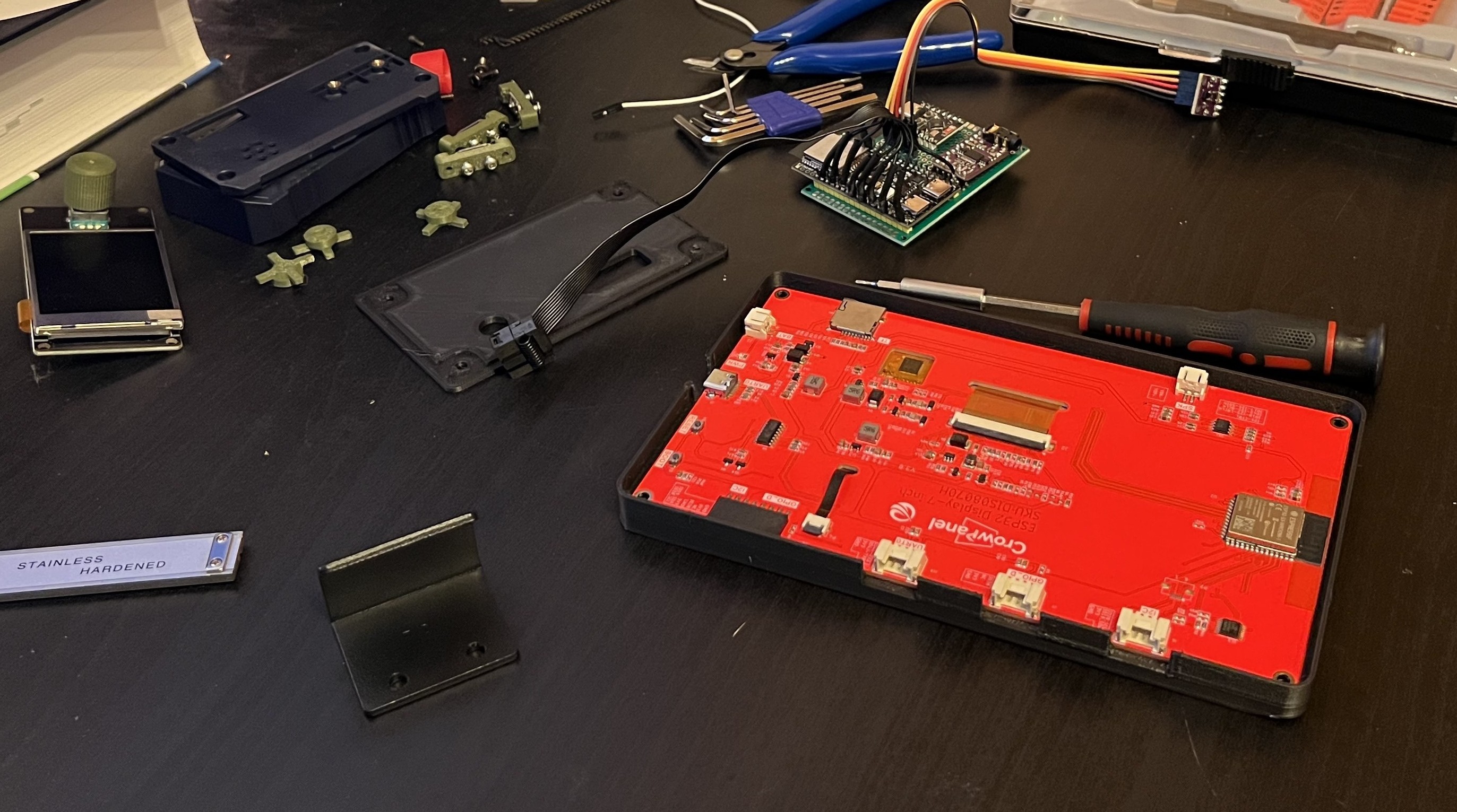
Also the case for the touchscreen finished printing and got mounted!
July 11th
A new SKR pico arrived! Also the touch screen from elecrow arrived and I designed a case for it! (And got sidetracked by another project)
July 10th
The SKR picos arrived! And one was used… **** you Amazon.
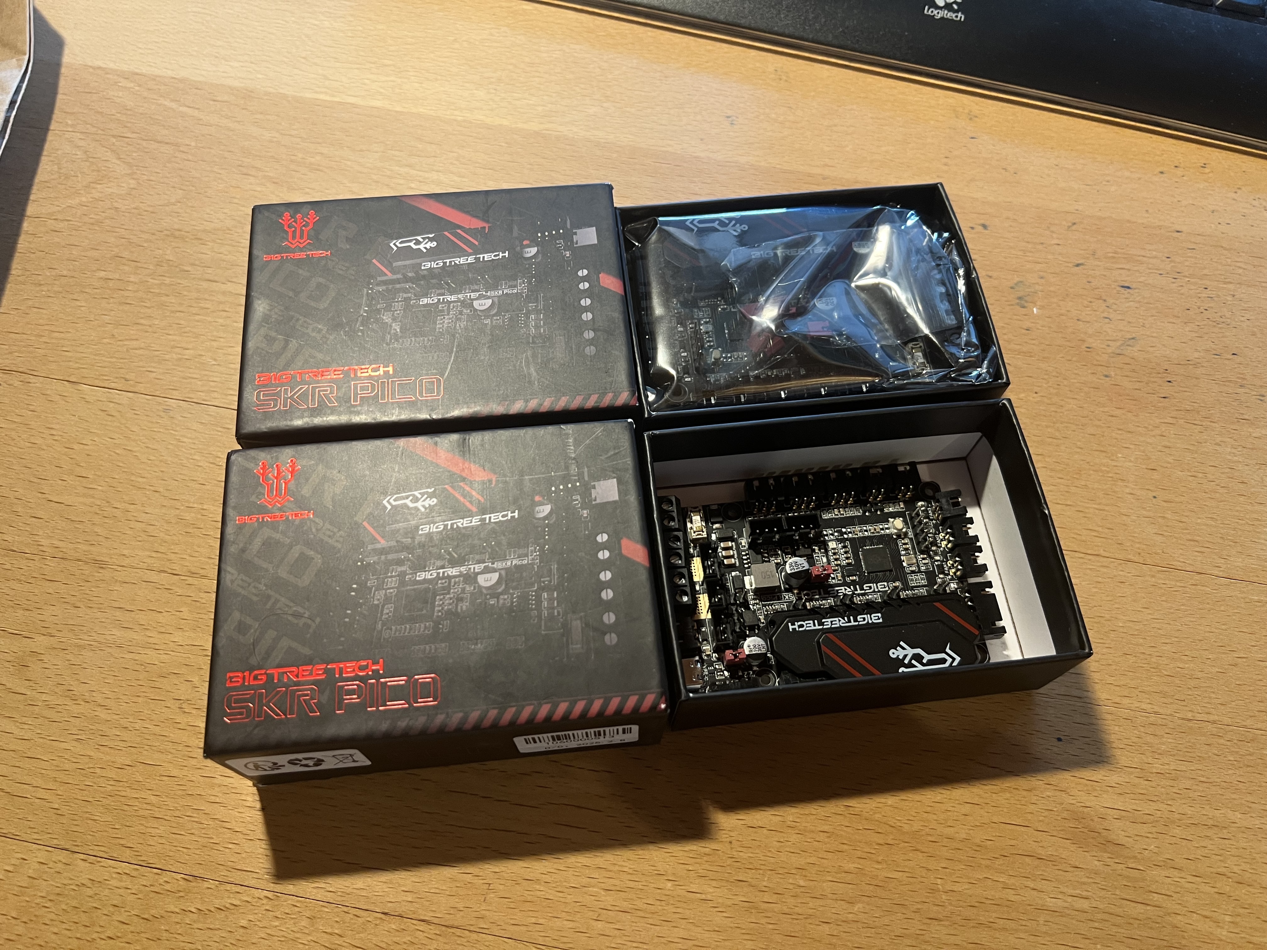
July 9th
After wasting even more time with SWD I just bought (and overpaid for) two BTT SKR picos on amazon with next day delivery. (I also bough a proper [clone] ST-Link debugging adapter from aliexpress that will arrive at sometime)
July 8th
Desperately tired to install klipper on the two TriGorilla V_4.0.1 (the control boards from the defective printers)… Turns out this specific board uses the GD32f303RGT6 mcu with a broken bootloader - so you cannot flash it. I tried tons of different SD cards, different klipper build targets, and flashing them via SWD using a debugprobe (a rpi pico running some firmware) using openocd. I once managed to “successfully” flash the original manufacture firmware back onto it:
sudo openocd -f flash_config.cfg -c "program original.bin 0x08000000 verify reset exit"Open On-Chip Debugger 0.12.0Licensed under GNU GPL v2For bug reports, read[...]xPSR: 0x01000000 pc: 0xfffffffe msp: 0xfffffffc** Programming Started **Info : device id = 0x21040430Warn : STM32 flash size failed, probe inaccurate - assuming 1024k flashInfo : flash size = 512 KiBWarn : Adding extra erase range, 0x0805b534 .. 0x0805b7ff** Programming Finished **** Verify Started **** Verified OK **** Resetting Target **shutdown command invokedBut it didn’t turn on anymore… For some reason some person decided that disabling the SWD-reset wire in the rp2040 version of the debugprobe firmware would be a good idea, so if you need that (which you do!), delete the #if false and #endif line in this file and recompile it!
I also had a extremely hard time connecting to the chip via SWD, since the reset (with the lines remove) still only worked in about ~10% of the tries…
July 7th
Designed & build a little wire extending box for the steppers on the left side & chaotic wiring.
July 1st
Added fans for electronics section, started wiring for Y-Gantry & Z-Motors.
June 26th
Back from holiday!
Did the Mains & 24V wiring (which didn’t blow up!) using a old power cord that now doesn’t exist anymore.
June 1st-10th
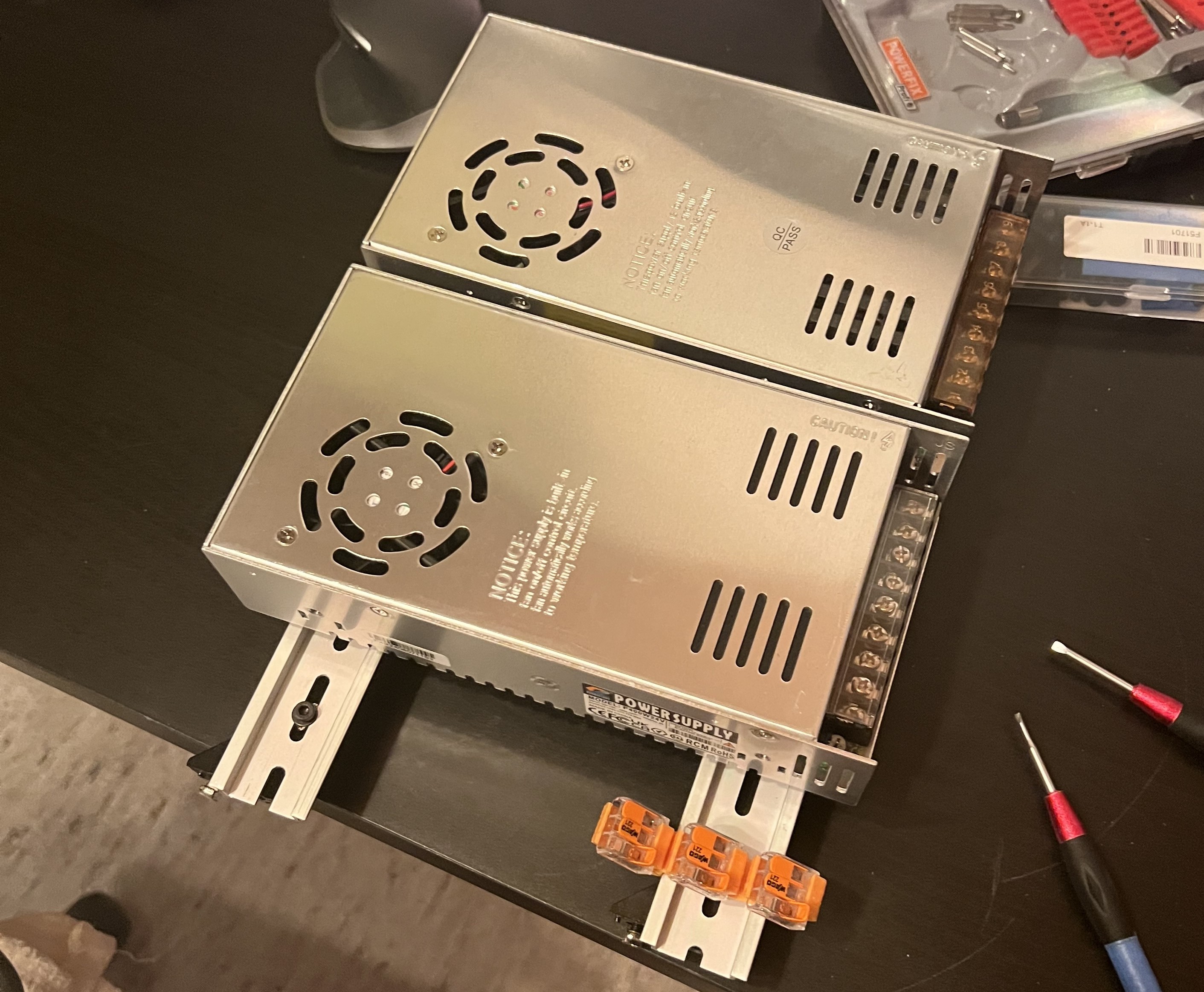
Still in the final exam phase, so not that much progress, BUT: I mounted the PSUs (yep, 2), the original control boards (from the 2 broken printers) and other stuff including the electronics enclosure.
(Made no picture of them, see next entry)
May 21th
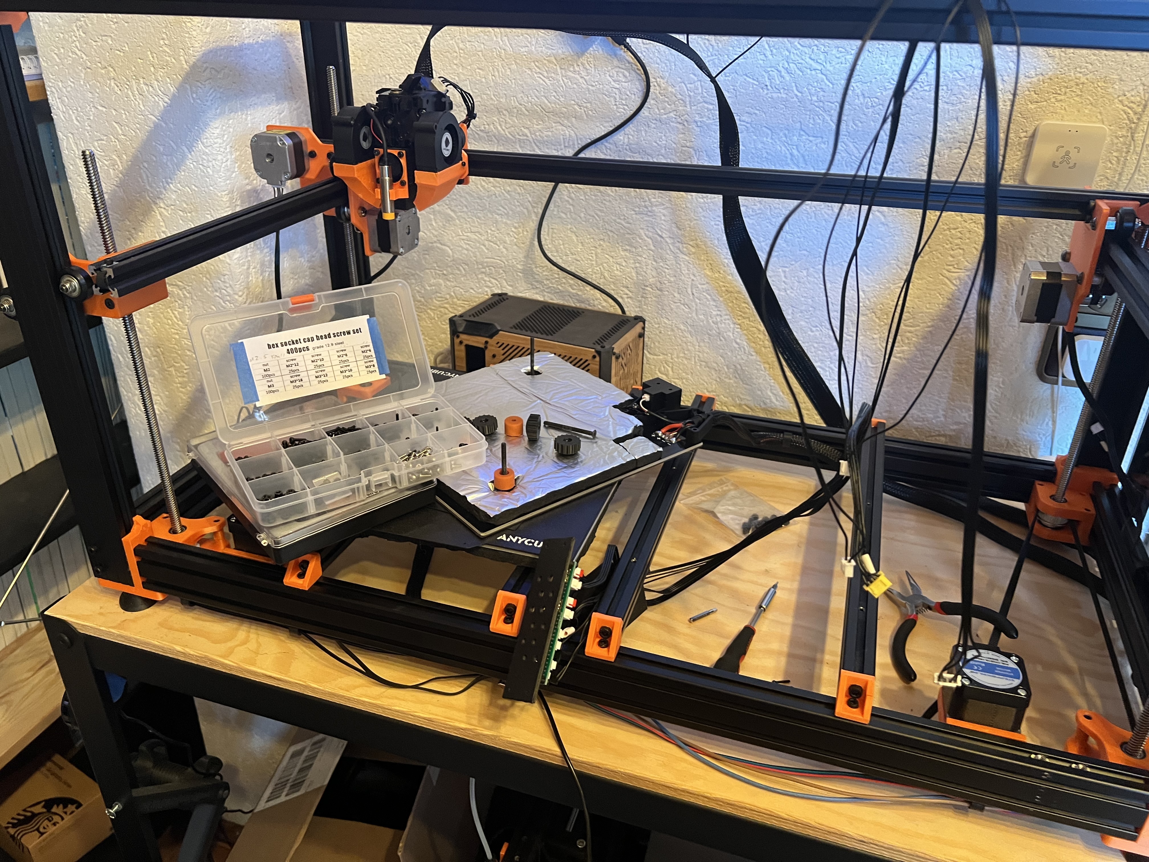
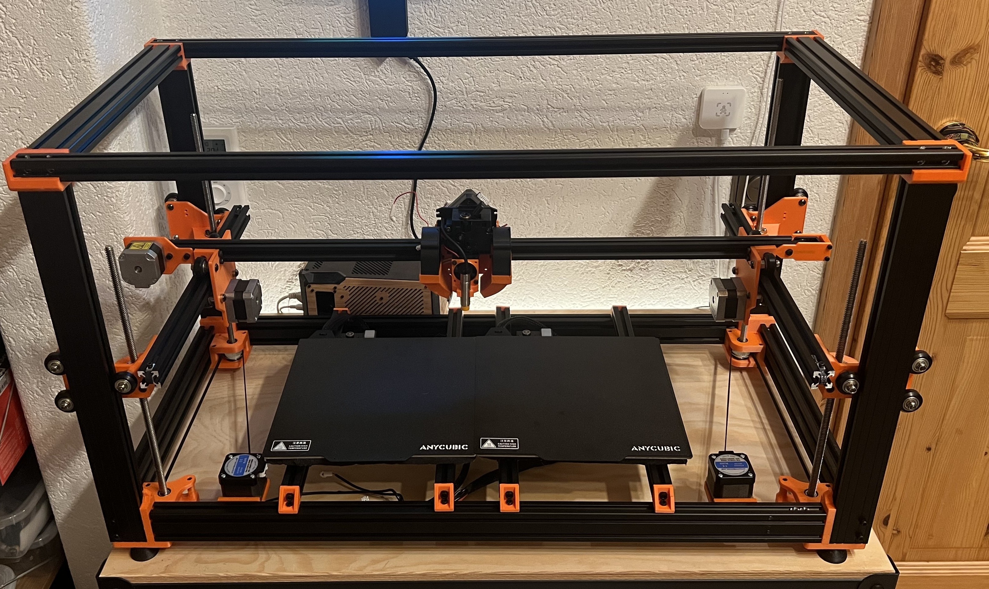
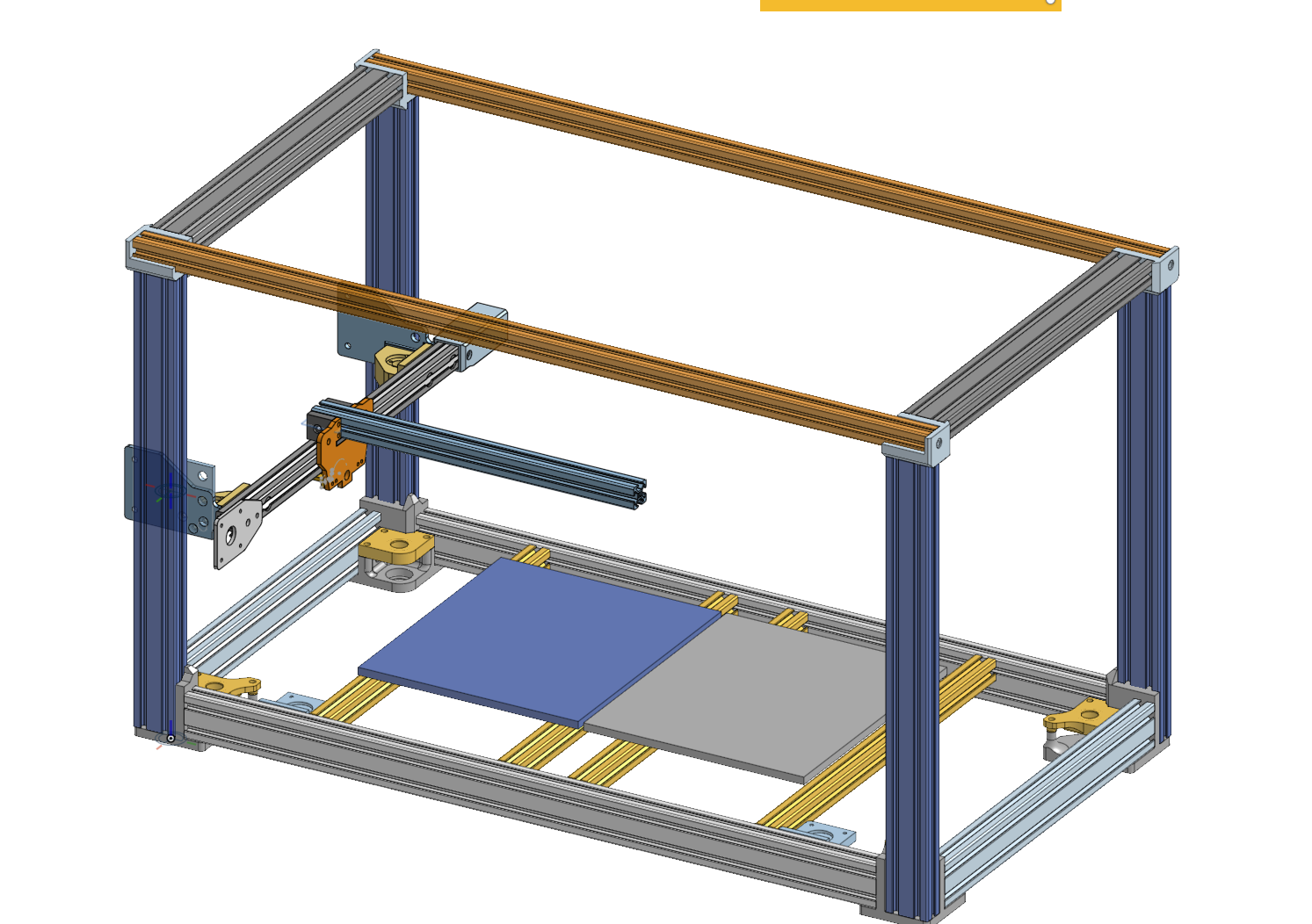
Insulated & mounted the beds & assembled and installed the XY-Gantry (using the subassemblies from before).
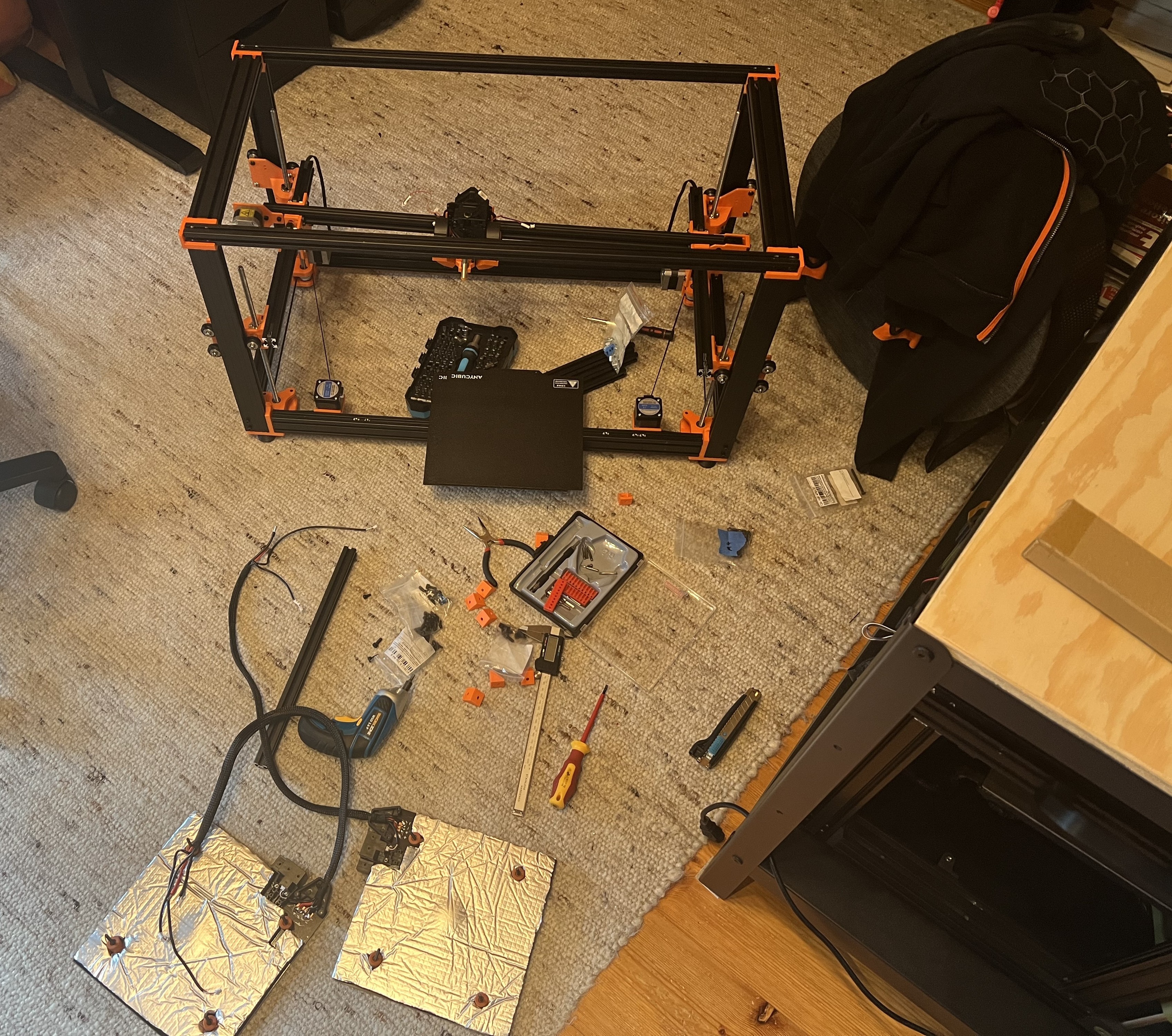
I’m really happy with how the design turned out!
May 20th
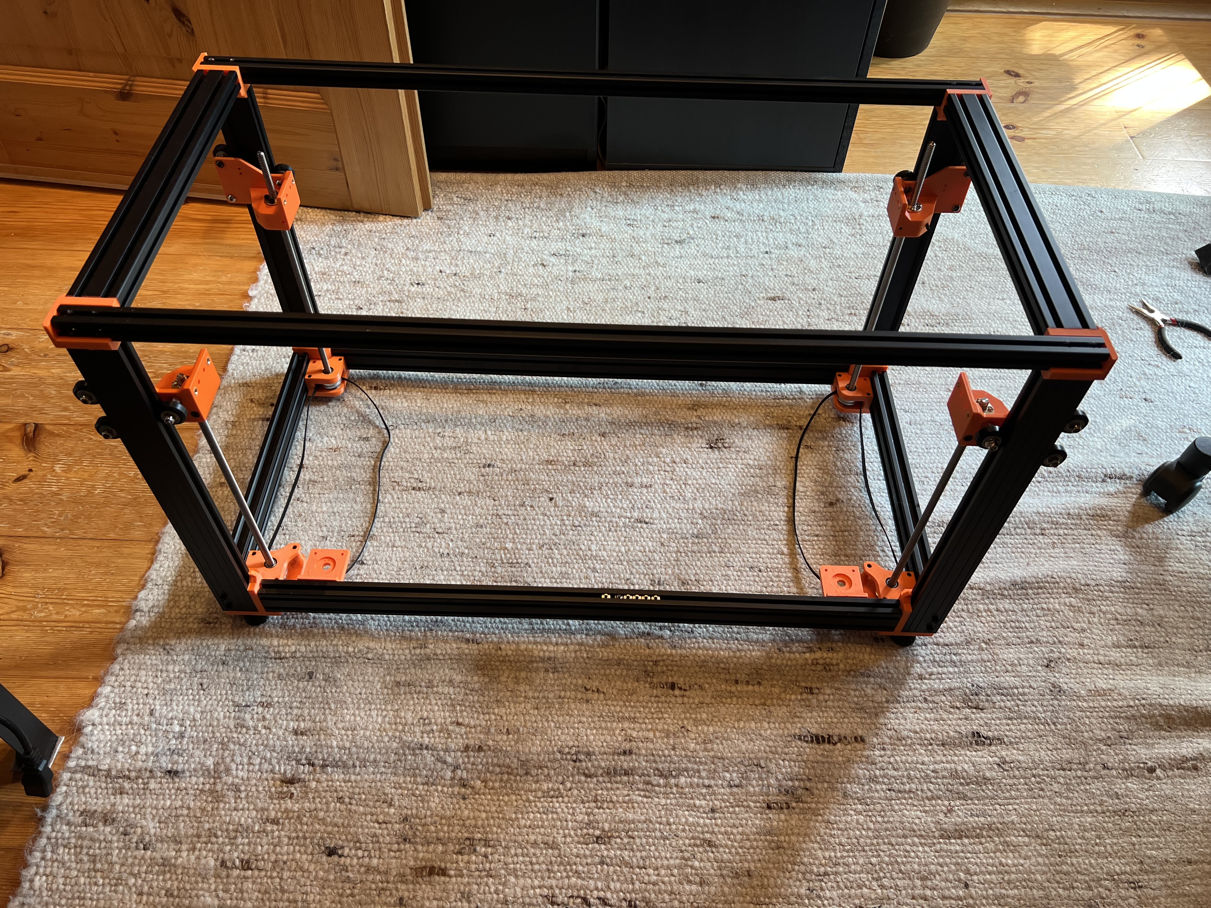
Assembled the top part of the frame - Not much more to say, apart from that my taps weren’t perfect (which meant that I couldn’t use all screwholes, but who cares… It will be strong enough anyway right… right ?)
May 19th
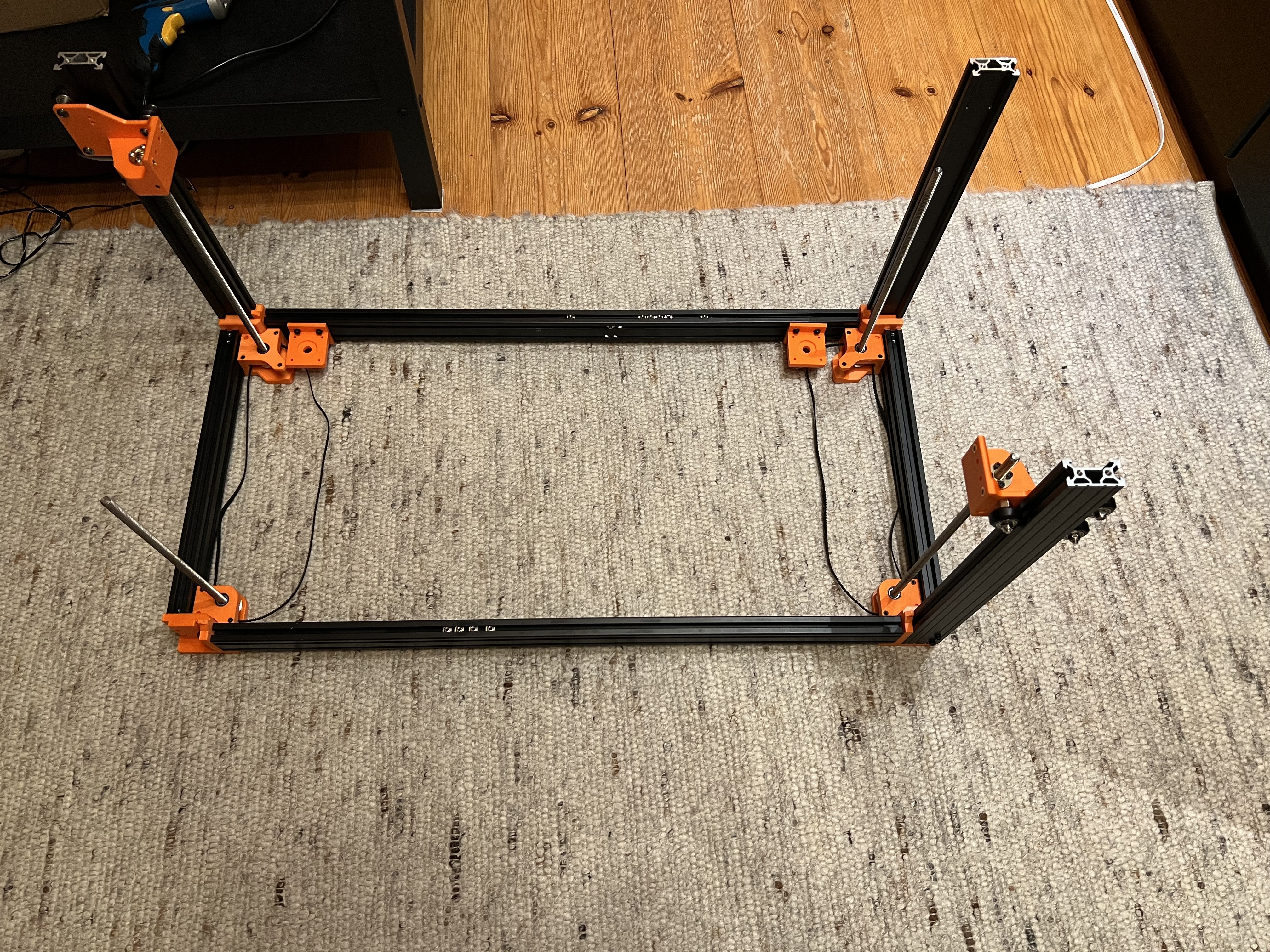
Assembled the bottom part of the frame! With enough force every fitted together nicely and it’s also somewhat square, i’d call that good enough.
Foreshadowing: The leadscrew in the top left (which was a spare I had lying around) has the wrong pitch…
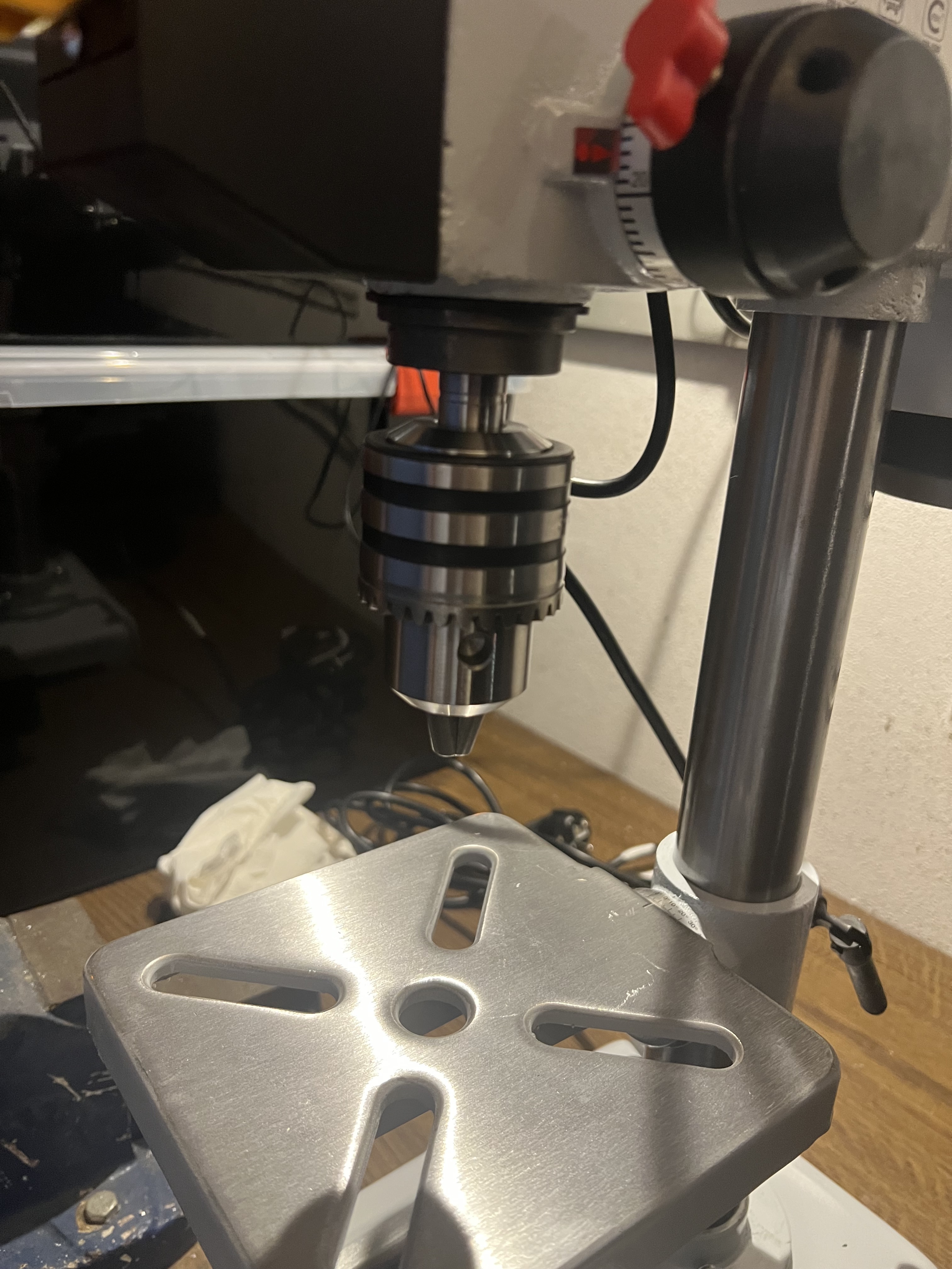
May 15th
Assembling the new drill press, and drilling all the left over holes in 1h… I hate that cnc
May 14th
I’m so done with aluminum profiles, I should have just payed ~$50 more to have them to the drilling and tapping.
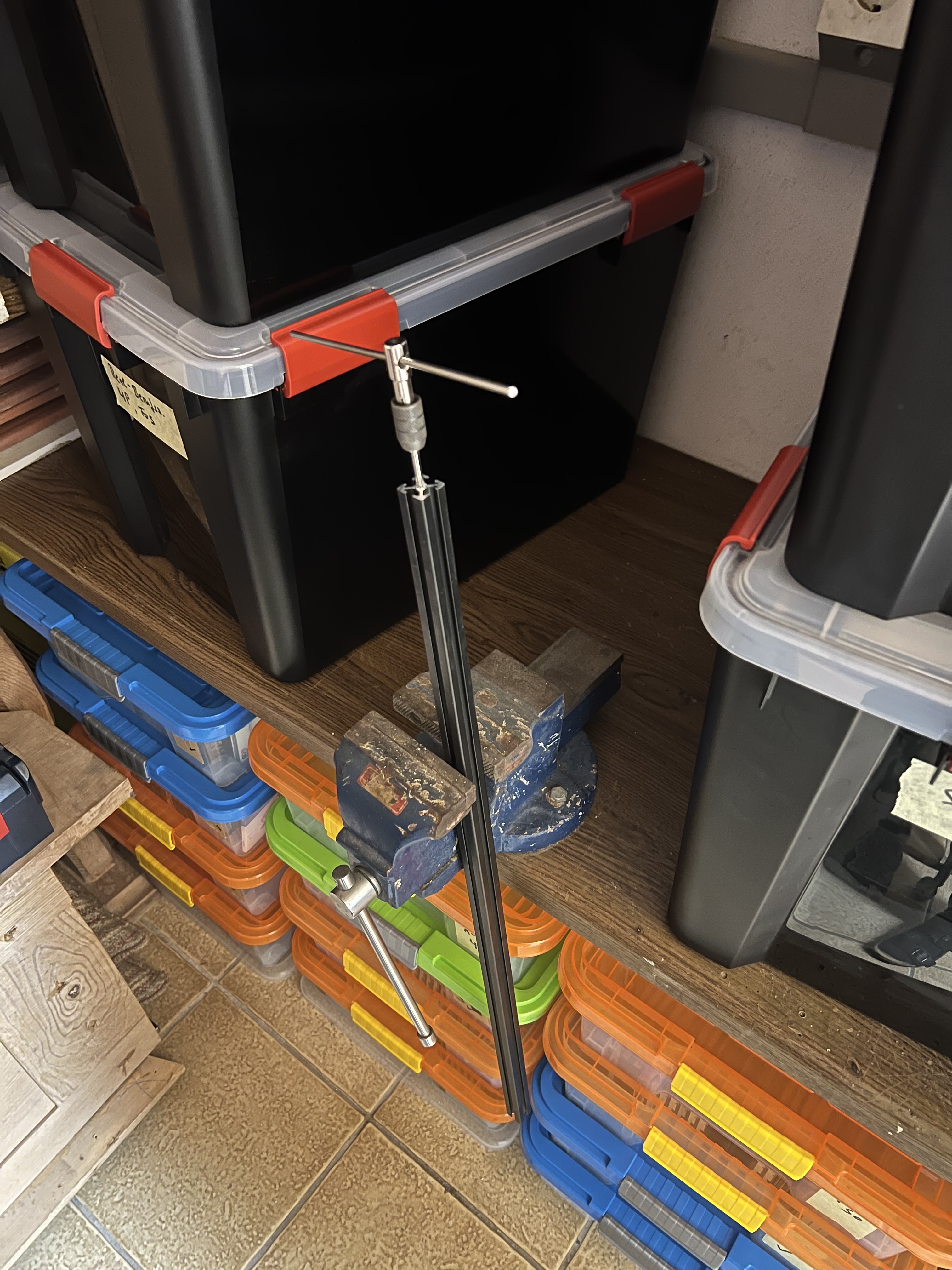
May 13th
Tapping & Drilling - Fun…
To save money I decided to tap all aluminum proifles and drill all necessary blind holes in them myself. There were a lot of taps and holes - and I though that using a (already heavily modded!) 3018 CNC for drilling the holes would be a good option…

It worked (i’ll give it that much), but it took around 10min per hole with a feed rate of a staggering 2mm/min… Cannot recommend
Tapping the ends of the extrutions turned out to be a rabit hole too: [this is not made up!]
- After tapping ~10 holes the $1.80 tapping tool from aliexpress got dull… -> Ordered new ones form aliexpress
- Same day, since I didn’t want to pause for a week until they arrive: Buying a new tap from the local hardware store only for it to snap in half after 3 holes (to be precise, IN the 3rd hole, it’s still in there)
- Still same day: Getting a new tap from the local hardware store only for it to snap in half after 2 holes (to be precise, IN the 2nd hole, it’s still in there) - yes
- Still still same day: Getting a new tap from the local hardware store (my third time today being there) only for me to be too scared to use it
- Still same day, same hardware store visit as above (at ~19:40): Impulse buying the cheapest drill press since I don’t want to use that cnc anymore
May 11th
Assembled all smaller subassemblies + the camera mod for the Ender3NG, lot’s of heat-set inserts (Hackadot leak)
May 4th
More printing over the last few days, most parts have now arrived - So far everything seems to fit together
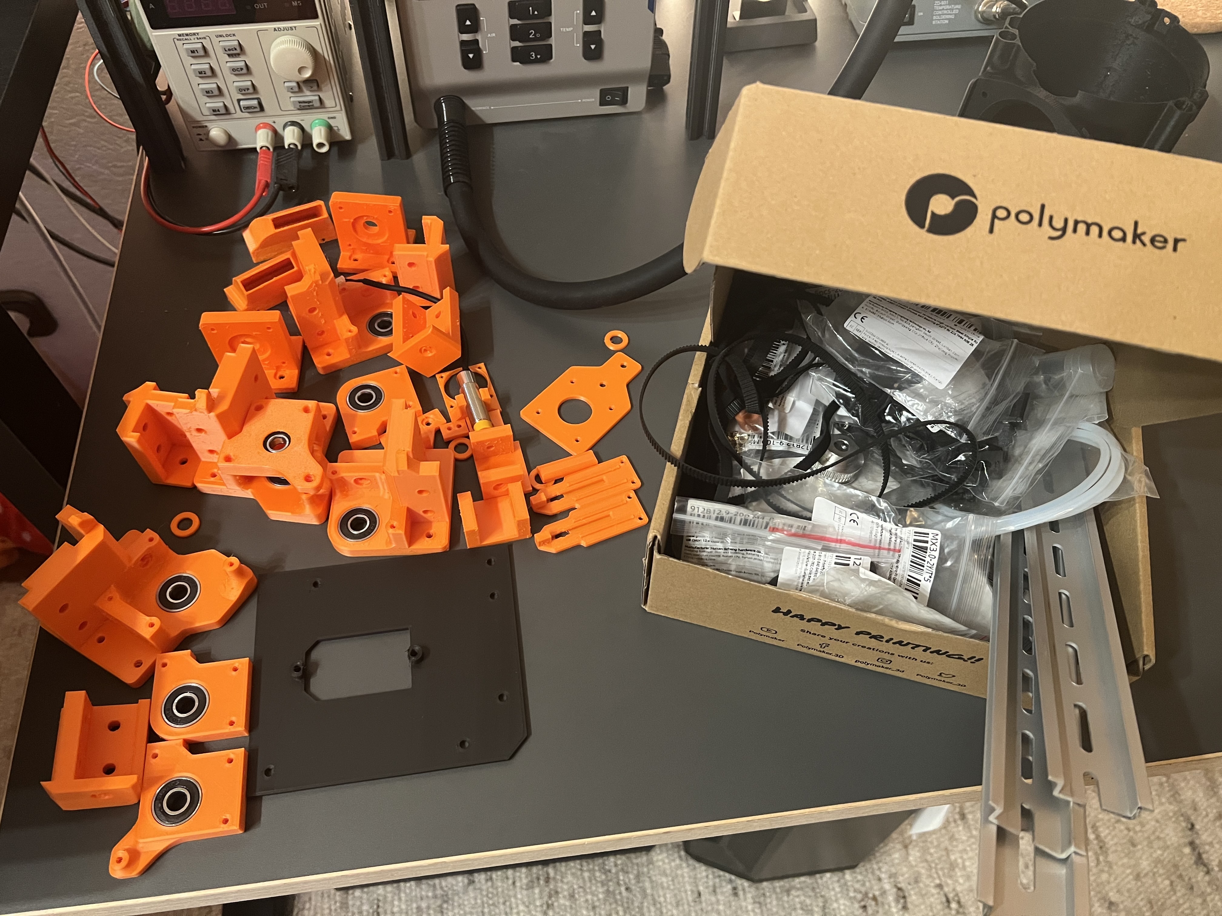
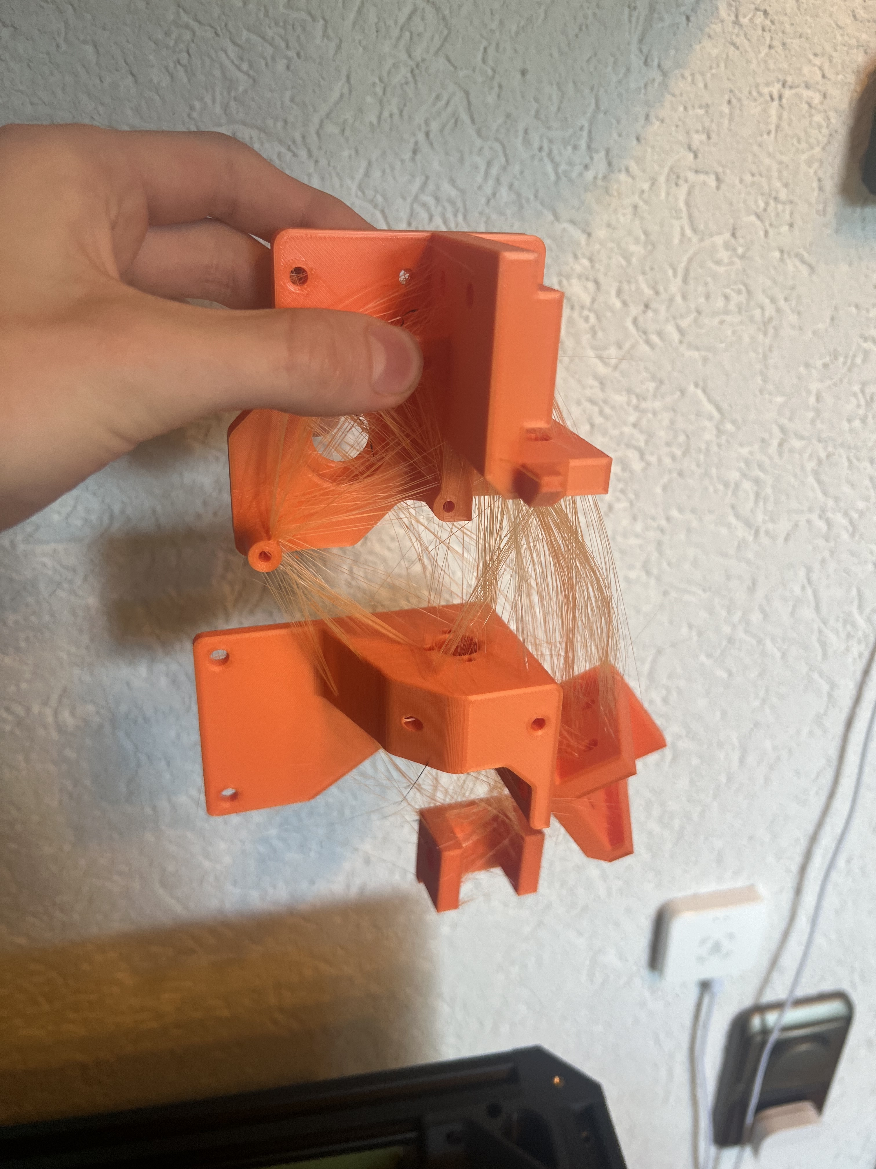
Rest of April
Not much progress here, due to final High school exams - Started printing parts towards the end of April, and rage bought the cheapest 2 role filament dryer (Sovol SH01) since the parts looked like this:
Phase 2: Design
[Written on April 7]
Take a look at the Design-Notes to better understand my design decisions!
Take a look at the PCB!
[Written on April 7]
About this part of the journal: So journaling didn’t really work out that well. I started planning the printer and a timeline ~4 weeks ago on March 9., but then got sidetracked by other things (hackboard, pre-final school exams, irl stuff). During this time I constantly thought about it though, and decided to try to convert 2 broken Anycubic Kobra 2 Neos into this one big printer, instead of buying all parts brand new.
After all, this project was a lot of fun and very interesting. Once I got into the “CAD design mood” I really enjoyed doing it, and I’ve also learned a lot about Onshape and how to approach big projects and design parts, that are internally dependant on each other. I’m proud of the final design :)
April 8th - Tuesday (1 day after deadline)
Small improvements & fixes: Improved ‘Design notes’, fixed spelling mistakes, added JST cables to BOM, added PCB mount to CAD model
April 7th - Monday (today)
I really want a break from cad plsss!
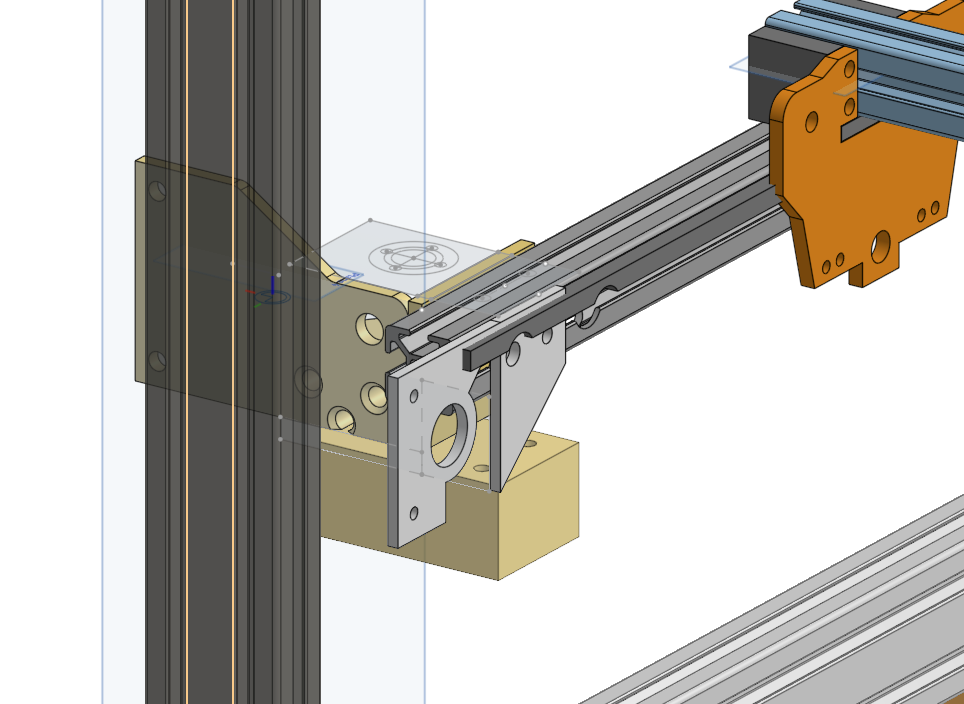
Today I fixed a lot of small stuff in the CAD model: I added endstops for X&Y, a X-Motor mount, X-Belt tensioner, changed Y-Motor position from fixed at one end of the extrusion to on the X-Plate, improved dummy models of steppers/lead screws/etc, fixed a lot of small bugs in the CAD model, created the PTFE tube holder and created the electronic housing.
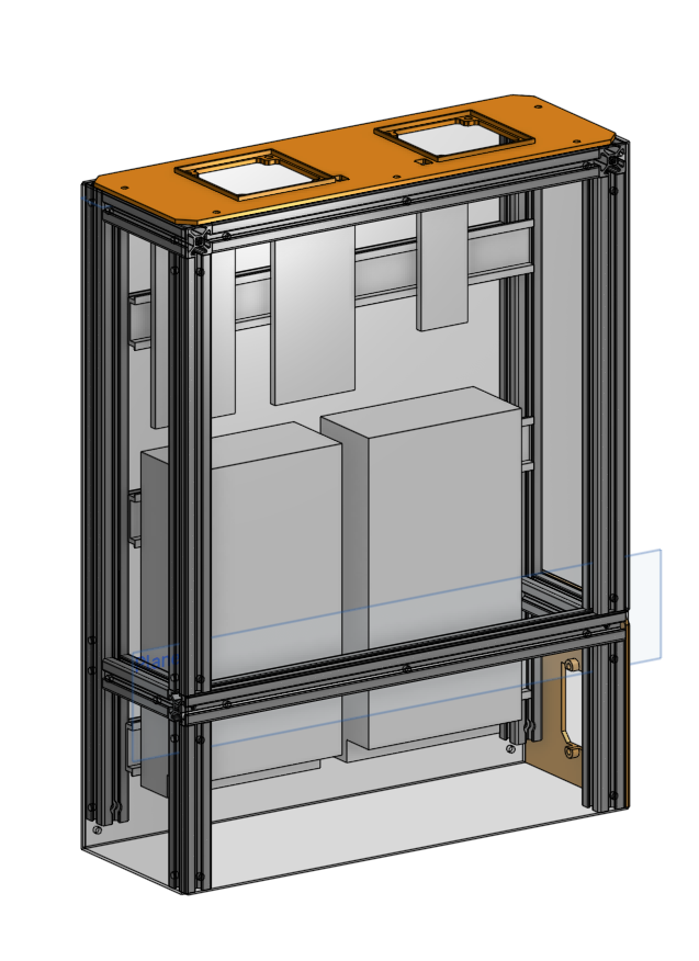
The electronics housing safely mounts both PSU, control boards, rpi zero and power plug. It’s surrounded by acrylic panels, and has two fans at the top to suck in air from the bottom though the entire assembly.
I also updated the BOM and created this document (and it’s now past midnight).
Final version (V2.1 in CAD document history):
Time spend in CAD: Last 7h (had to go to school until 13:10 to get grades of last 2 years and the admission notice for my final 5 tests)
April 6th - Sunday
Another caddy day (ahhhh)
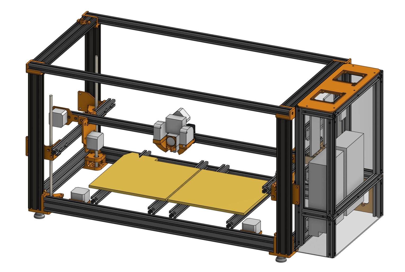
This day was super productive. I’ve designed the entire toolhead, reworked the entire gantry, and finally managed to create a draggable 3 dimensional toolhead in onshape, that allows me to test the reachable positions of the nozzle.
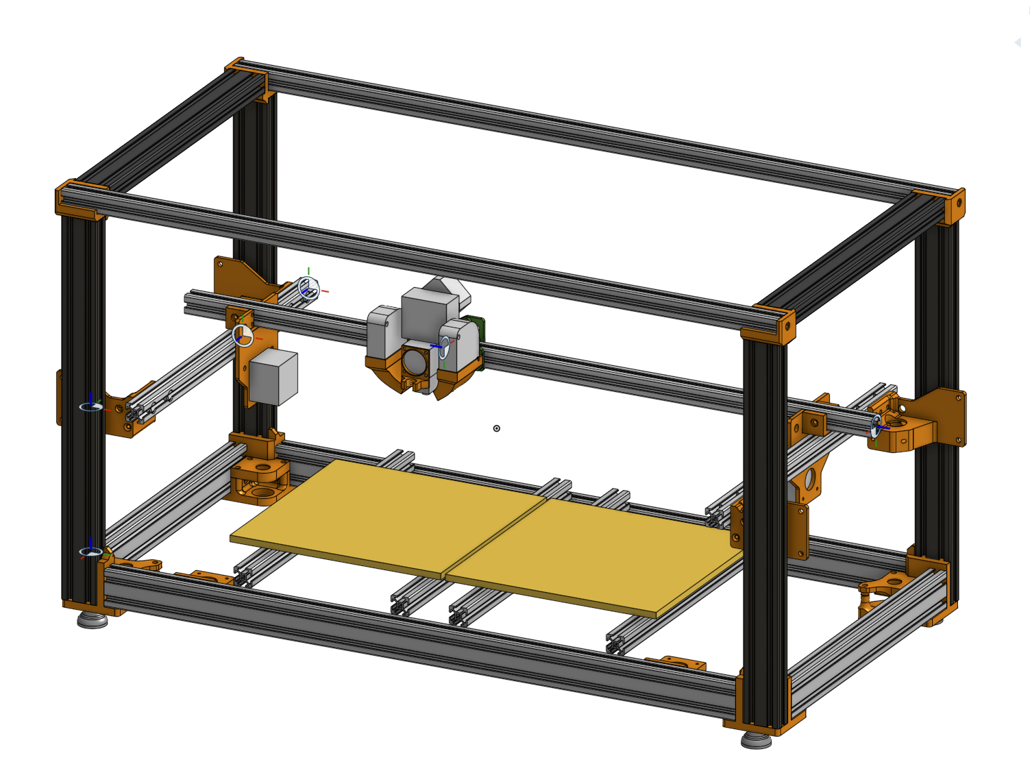
Reworking the gantry was a lot of pain. This is my first time seriously using assemblies in Onshape, and I based the original gantry part assembly on a feature I deleted while reworking the frame (ahhh). This broke my entire gantry when I finally updated it’s context, which I need to do, because I’ve extended it by ~8cm to allow the nozzle to reach all positions. This is a example of the pain I had to endure:
Time spend in CAD: ~75% of my time awake (didn’t even go outside) -> 10h
April 5th - Saturday
A caddy day
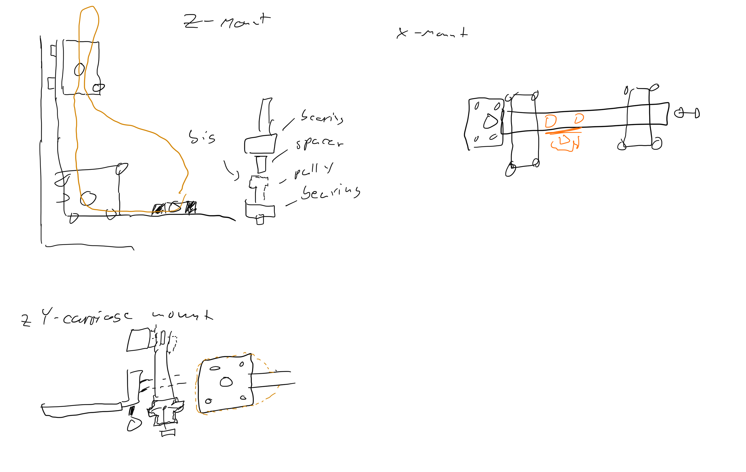
On saturday I basically redid everything I did the day before. Instead of bolting the profiles strait to each other using blind joints, I took some inspiration of the Ender3NG, and created these “in-between structures” (see picture). I also converted this sketch (which I created the night before) into CAD (once again, inspired by the Ender3NG, but created from scratch and the final part also ended up completely different)!
I’m very happy with the progress one that day, cause the frame and gantry has been one of these low motivation, hard to imagine progress blockers. Also, the top “extrusion structure mounts” worked first time, and I never had to change them later
Time spend in CAD: ~60% of my time awake (pain, at least I managed to sit outside and enjoy the warm weather for 30min) -> 9-10h
April 4th - Friday
4 Days ago I finally started to speedrun the entire CAD design starting with the frame (which I then redid one day later…). I started by converted these drawing I made about two weeks earlier during school into this frame:
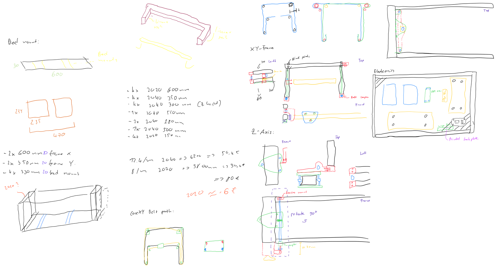
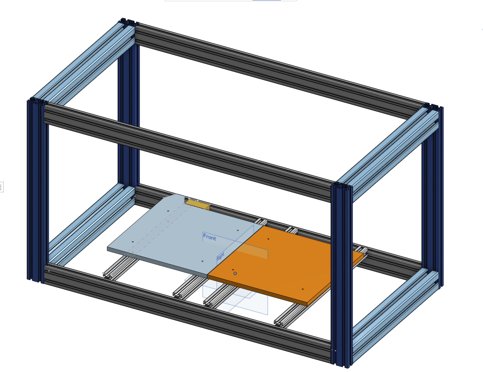
As you can see in the sketches, I was initially targeting a CoreXY build with linear rails, but this idea later got ditched in favor of a simple V-Wheel based Belted XY-Gantry to keep costs down.
I also started dissembling one of the broken printers to take measurements of the heatbed, etc.
Time spend in CAD: 2h during the morning (since I’m almost done with school, I don’t have to go to every lesson anymore), 6h in the afternoon, evening and early night.
Phase 1: Planning
Note from July 17: This plan got totally ignored
Features:
| Must-have | Should-have | Probably not enough time |
|---|---|---|
| (400mm)² for X&Y, Z should have 200mm+ | Filament runout sensor | 2 Build-in filament holders (Prusa Core style: inset into case, on the left&right) |
| CoreXY with Belts | LED-Bar under Bed for status, etc | Build-in filament weight sensor (using one of these) |
| Enclosed (for ABS) | Exhaust air filtration using activated carbon | External Multi-filament switcher (Pico-MMU, 2 filaments) |
| Direct drive | ||
| ABL using cheap BLTouch clone | ||
| Temperature Sensor inside & Temp-control fans |
March 8th - Saturday
Brainstorming about goal. Final 3 candidates:
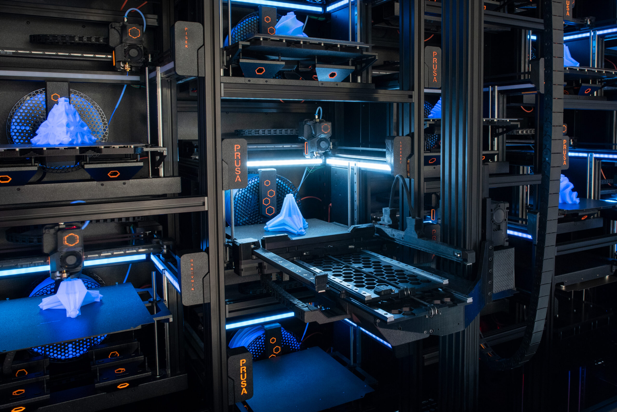
- Print farm: Similar to this - Why not: Basically would only copy their design and scale it down, due to budget only 2 integrated printers -> kinda useless
- Module based: 250x250x100mm modules with only the heated, joinable in one direction, rack & pinion system on the sides, hotend on a “crane” (picture explains it best) - Why not: Budget would only allow ~2 modules -> Print volume way to small
- Billig (this): There seems to be no big (~(400mm)³) enclosed printer for under 1k -> Should be doable with only 300$ when cutting corners
Billig will be a mix of:
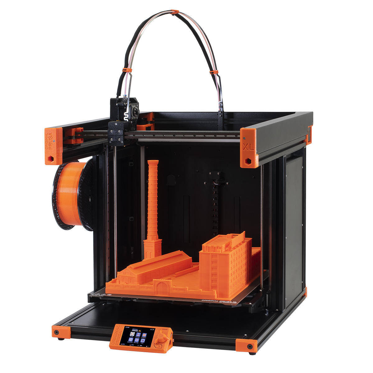
- Prusa XL (frame design)
- Voron 2.4 (artistic style)
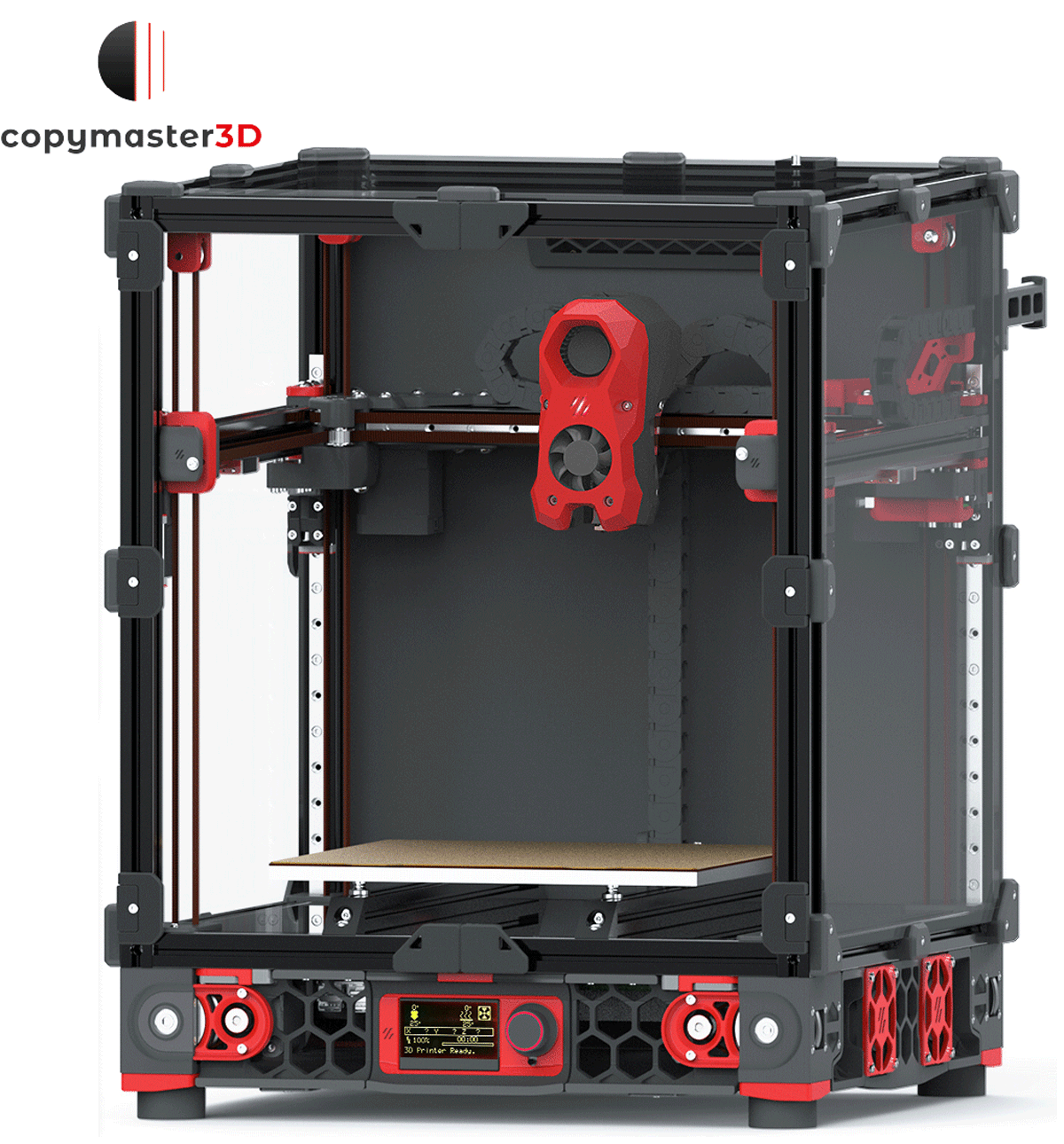
- Ender 3 NG (enclosure design)
Accepted tradeoffs:
- Longevity: Will be using the cheapest parts for everything
- Print speed: Won’t be fast due to size
- Power draw: Will need A LOT of energy to heatup the entire chamber
Initial design ideas:
- Printbed consist of 4 smaller (and cheaper) print beds: ~ 40€ total
Time: 3h
This was a triumph, Huge success