CageHome3D
Made by: @chunyinkwong // https://github.com/chunyinkwong/
Repository link: https://github.com/chunyinkwong/infill-journal
Total hours so far: 47
- I have access to 3D printing facilities and am able to obtain printed models on or before March 21st.
Information
This printer is a CoreXZ bed slinger 3D printer designed to be easily stored after usage. The problem I tried to solve is when living in a small apartment, a 3D printer takes up a relatively a lot of space. Furthermore, my 3D printers aren’t being used that often. Thus, I wanted to store my 3D printer in a space efficient way, while keeping a large print area.
My final idea is to have parts of the printer easily removable so it can be stored flush to the wall without taking up too much space. The final design has 4 captive screws and 3 wire clips to disconnect before separating into 2 pieces that can be stored flat.
I decided on a bed slinger design because it only has 2 vertical extrusions to remove. I decided on a CoreXZ system, because leadscrews would be hard to remove.
Furthermore, this printer is powered by USB-C PD 3.1. This means you will need a 28V 140W compatible charger, eg Macbook Pro charger to power it. This is because I found 24V PSUs to be giant and clunky, whereas a USB C sink is small and cheap.
Instructions to build
Follow the CAD. You’ll need to determine a good place to screw on the electronics on a piece of wood.
Notes:
- There are no screws modelled in the CAD, but the depth of the screwholes are modelled.
- There are no belts modelled, just follow the CoreXZ belting.
- You will need to crimp the wires on the stepper motor and connect them to a clipped wire connector for easy removal later on.
- Route the wires carefully through the molex connectors
Wiring diagram

Disassembly instructions
- The screws are captive screws, meaning they won’t fall out
- Can’t see the video? Try upgrading your browser to one that supports AV1 files
- Can’t see the video? Try upgrading your browser to one that supports AV1 files
BOM
| Part | Qty | Unit Price (RMB) | Final Price (USD) | Link |
|---|---|---|---|---|
| 2040 300 Aluminum extrusions | 2 | 20.18 | 5.65 | CNC D Prin…-Taobao Singapore |
| 2020 400 Aluminum extrusions | 2 | 12.50 | 3.50 | 100-800MM …-Taobao |
| 2020 340 Aluminum extrusions | 4 | 30.29 | 16.96 | 4pcs/lot 2…-Taobao |
| MGN12 Linear Rails 300mm + Carriage | 3 | 73.00 | 30.66 | 1PC High P…-Taobao |
| M3x8 Screws | 30 | 0.50 | 2.10 | M2M3 M2.5 …-Taobao |
| 15mm Diameter Flanged Ball Bearings | 16 | 1.50 | 3.36 | Promotional High Quality Flange Bearing F695-2Rs 5*13*4mm F695Rs 3D Printer Bearing Cup Type-Taobao |
| 1mm Washers | 6 | 0.00 | 0.00 | (at home) |
| Open timing belts 6mm, 2mm, 800mm | 2 | 20.50 | 5.74 | 2pcs 20T G…-Taobao |
| Open timing belts 6mm, 2mm, 400mm | 1 | 20.50 | 2.87 | 2GT-6mm橡膠開…-Taobao |
| Belt tensioners | 6 | 0.00 | 0.00 | (included in above) |
| Limit switches | 3 | 2.76 | 1.16 | https://world.taobao.com/item/680045689973.htm |
| NEMA17 Stepper Motors | 3 | 39.00 | 16.38 | 42步進馬達 NEM…-Taobao |
| GT2 Pulleys 20 tooth | 3 | 0.00 | 0.00 | (included in above) |
| Sherpa Mini | 1 | 129.00 | 18.06 | 5pcs Mini …-Taobao |
| E3D v6 Clone | 1 | 13.00 | 1.82 | E3D V6沃龍vo…-Taobao |
| 4010 fans | 2 | 15.98 | 4.47 | CAIZHU-FAN…-Taobao |
| SKR Mini v3 Mainboard | 1 | 358.00 | 50.12 | BIGTREETEC…-Taobao |
| Raspberry Pi 4B | 1 | 0.00 | 0.00 | (at home) |
| USB PD 140W Sink Board | 1 | 4.38 | 140W USB-C Fast Charge Trigger Board Module PD/QC Decoy Board USB Type-c PD3.1Power Delivery Boost Module 28V/36V/48V - AliExpress 13 | |
| USB C 140W charger | 1 | 0.00 | 0.00 | (at home) |
| Piece of wood (to screw electronics on) | 1 | 0.00 | 0.00 | (at home) |
| Heated bed 220x200mm | 1 | 55.84 | 7.82 | 3D打印机热床MK3铝基板DIY套件Reprap加热板铝板平台配件带线套装-淘宝网 |
| PEI Sheet | 1 | 44.50 | 6.23 | TZ拓竹子3D打印双…-Taobao |
| Magnets | 4 | 0.00 | 0.00 | (at home) |
| Piece of wood (to hold the bed to carriage) | 1 | 0.00 | 0.00 | (at home) |
| 6mm Spacers | 4 | 0.30 | 0.17 | TZ拓竹子3D打印双…-Taobao |
| M5x16 captive screws | 4 | 4.25 | M2 M2.5 M3 M4 M5 M6 M8 GB839 304 Stainless Steel Short Head Slotted Captive Hand Screw Knurled Thumb Anti-loosening Screws Bolts - AliExpress | |
| M3x30 screws | 12 | 0.50 | 0.84 | M2M3 M2.5 …-Taobao |
| M3x12 screws | 20 | 0.50 | 1.40 | M2M3 M2.5 …-Taobao |
| M5x40 screws | 4 | 0.50 | 0.28 | M2M3 M2.5 …-Taobao |
| M5x10 screws | 20 | 0.50 | 1.40 | M2M3 M2.5 …-Taobao |
| Misc screws (dw cainiao deliver in 2 days) | 1 | 50.00 | 7.00 | (at home? or just buy as needed) |
| Total | 189.62 |
Journal
26th February 2025
Research: 1 hour (brainstorming + printer type researching)
Brainstorming ideas, first draft idea selected: A foldable 3D printer that is able to be stored within an small apartment.
Draft specifications
- Should fold flat so it can be stored nearly flush to the wall
- Be easily unfoldable without any tools
- Have a heated bed
- Be able to print PLA
- Moderate speed (50-150mm/s)
TBD, in progress
Printer type:
- CoreXY
- Pros
- Fast print speed
- Cons
- Has a belt which might be hard to tension after folding and unfolding
- Pros
- Cantilever
- Pros
- Compact
- Cons
- Stability issues
- Pros
- Rectilinear
5th March 2025
CAD: 1 hour
Installed Fusion360 and watched some tutorials on how to use CAD software
12th March 2025
Spent 2.5 hours trying to CAD a toolhead, realized that I have no clue that I am doing.
Probably should’ve started on the gantry and frame first. This plan only took 30 mins and it’s more progress that I’ve made on the toolhead
Frame plan
Bed slinger 3D printer design
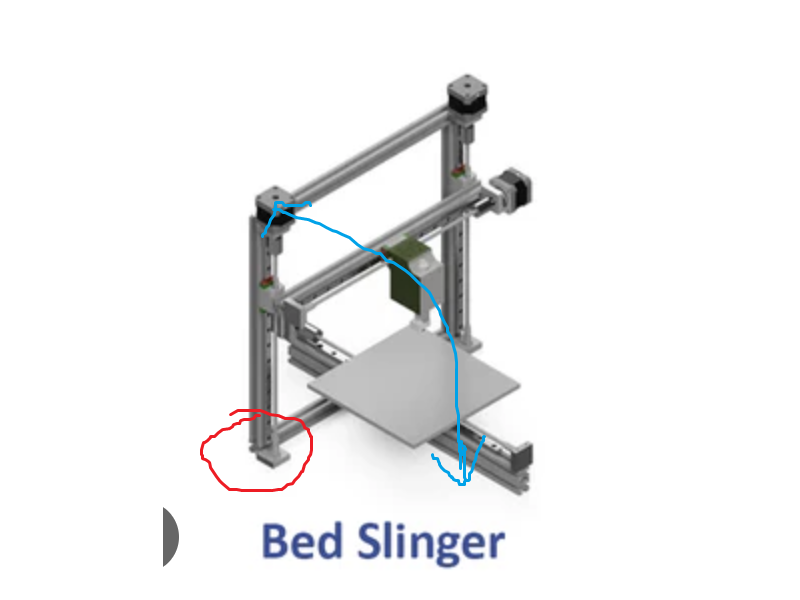
- Part circled in red should have some joint that allows it to fold
- The top of the frame will move along the blue arrow
- Ensure it actually folds flat given that the user manually moves the hotend to the top and the bed to one side after power off
- When opened, it shoud be locked into place and a stopper or something that ensures it is square
- Perhaps some spring locking mechanisms but I don’t know how any of that would work
- To close it, probably will be some button or something to hold down
- Probably should lock in place when shut as well
btw no clue how to design any of that in CAD brb gonna spend 6 hours later learning Fusion360
14th March 2025
Spent 3 hours learning Fusion360 again
22nd March 2025
Spent the last week learning CAD, took me 8 hours to make this (totally unrelated to the project, just to improve my CAD skills).
I think I am ready to actually design the things in CAD after a quick sketch of my ideas, hopefully a week is enough.
3rd April 2025
I got sick the last week, and had schoolwork, so didn’t make progress. 3 days remain.
I made the BOM with around 4 hours of research. Got feedback in Slack and tried to improve it further.
Feedback gotten
- Belts were closed loops and not adjustable length (oops)
- Bed selected isn’t a buildplate, so I either need magnets or a buildplate
- Choose a E3D V6 clone instead of the official one to save money (I was overbudget)
Realized that my original plan wouldn’t exactly work. Firstly, I couldn’t find a part that I wanted. I searched up knife hinge, locking hinge, pivot hinge, 90 degree hinge, spring loaded hinge with button to unlock, etc but I couldn’t get the part that I had in mind. Not sure what to search but I tried a long time.
Furthermore, I realized that if I have a rotating part, then that part would need to lock in place to avoid vibrations.
New plan: Make the Z axis removable with ease.
- Bed slinger design
- Belt only; no lead screw so there are less parts connected to be base
- Need to change the BOM, add a counterweight (decided on a Key-Bak, inspired by the Voron Switchwire) and remove the lead screw
- To disassemble, remove 4 captive screws and unplug the extruder wires
- Wires needs to have an external point to connect; a single action should disconnect the wires
- Captive/thumb screws are used so it doesn’t fall out and get lost. Also needs to be a thumb screw with a knob and knurling to make removal by hand easy.
- Z axis assembly parts
- X motor, belts, tensioner, pulley, etc (connected to the base with 2 captive screws)
- Z motor, belts, tensioner, counterweight, pulley etc. (connected to the base with 2 captive screws)
- Extruder, toolhead etc (connected to the base with wires)
- Filament and stand (connected to the extruder, not related to base)
- Base assembly
- Y motor, belt etc
- Heated bed
- PSU, electronics etc
- Frame (as small of a footprint as possible)
3 days of nonstop CAD is about to come >:)
4th April 2025
Got started building the CAD for the printer. I tried to cheap out on aluminium extrusions (ouch those are expensive) by using 2020 extrusions. Taking a look at other printers, I noticed lots of printers used 2040 or 3060 extrusions for the base. I wondered why until I realised how large the PSU was. I don’t want my printer to have a huge PSU sitting at the bottom, so I looked into other solutions.
I decided on using a USB-C PD 3.1 input. I already have a charger at home, and they are widely available (eg. Apple Macbook 140W USBC charger). Doing some research, I noticed that the PD specifications are 28V, 36V or 48V. As I own a 28V charger, I will go with that. More research shows that the maximum for the 28V spec is 140W. I don’t want to buy a 48V 240W charger just for this printer (they’re expensive).
Researching for USB PD 3.1 sinks, they’re tiny boards compared to the PSU. Really surprised they output 140W, considering the size of it.
Initially, I had 2 concerns.
- Will I accidentally fry the mainboard (SKR mini E3) and components connected to it?
- Will 140W be enough to heat a bed? (TriangleLAB 24V PRUSA i3 MK3 MK3S, which is 250x210mm)
To address the voltage issue on the mainboard, I looked into the SKR mini E3 schematic. After consulting with someone who knows what they’re doing, they told me to look at the VBB line after the DC input and the fuse. The components connected to the VBB line are
- MP1584EN, a DC-DC 5V converter, used to power the CPU and 5V output for the RPI, which is rated up to 28V.
- TMC2209, the stepper motor driver, which is rated for up to 29V.
- Extruder heater and bed heater. These are just resistors with no sensitive electronics, so they follow Ohm’s law etc, so P = V^2/R, so they won’t die or anything, just consume more power
- Fan headers and LED headers. It should be fine to run a 24V fan on 28V, it’s 17% over the rated voltage but it’s just a motor. I don’t plan to use the LED headers, but there are 28V LEDs available for purchase (unlike fans)
To adress the power issues, I did some research and came across a rough number of 0.4W per cm^2 of bed area. As I am using a 25x21 = 525cm^2 bed, it will draw around 210W of power, which the 140W won’t be able to sustain. I wasn’t planning to print ABS anyway, so perhaps I will resort to the gluestick method for printing PLA. However, I still want to buy the heated bed to see if it it’s possible, eg I put a cardboard box over it to insulate it and it may reach 60C for PLA.
Additionally, revised my plans a little bit. This is because the stepper motors are connected to the top assembly, while the wires for them are connected to the base assembly. I will need to find a connector for the wires which are accessible from the top as I don’t want to be flipping the thing over and disconnecting a USB from the RPI and the stepper motor from the mainboard. Therefore, the current action for disassembling the printer into 2 parts that can sit flush to a wall will be
- Unscrew the 4 captive screws connecting the gantry to the frame
- Unplug the 2 stepper motors
- Unplug the wires leading to the extruder
- Hopefully it’s really easy to lift up the gantry from the frame, and doesn’t require sliding around. However I looked at the captive screws and I don’t think they unscrew enough to totally lift off the frame, so it may have to slide along the slot in the aluminum extrusions
CAD Progress so far:
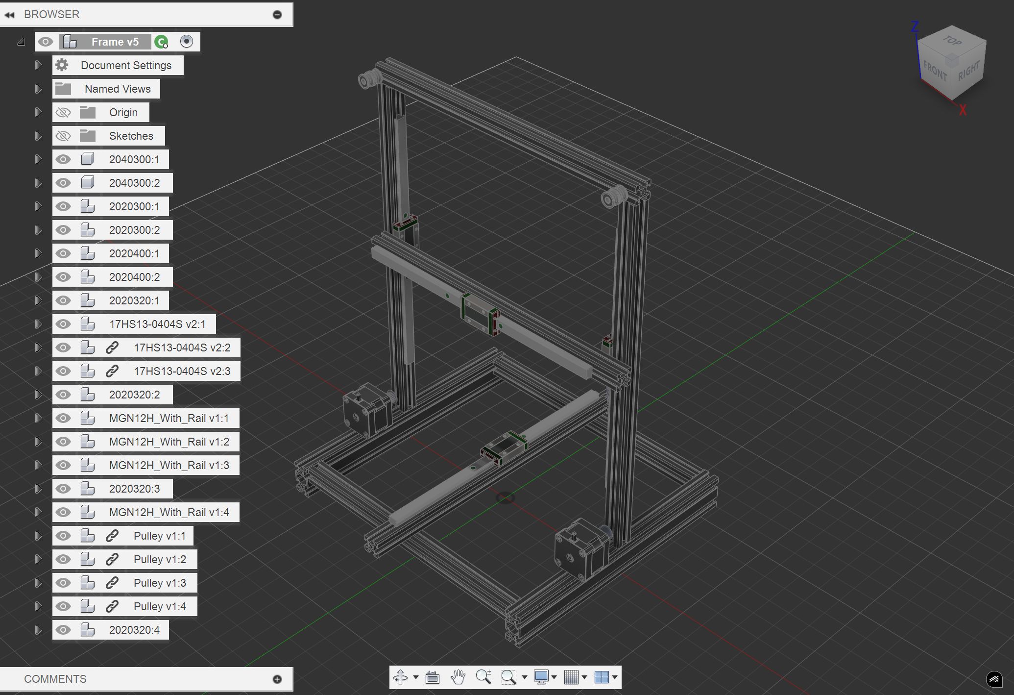
CAD TODO List (last updated on April 7th):
- [ x ] Top pulley connector (has 4 bearings for 2 belts and connects to the top of the printer)
- [ x ] XZ axis connector (has 4 bearings, connects to the Z carriages and redirects the belts 90 degrees to the X axis)
- [ x ] Y axis connector (connects Y motor to frame)
- [ x ] X, Y, and Z carriage endstops (should be just a cube or something, easy)
- [ x ] XZ stepper motor mount (contains belt tensioner, stepper motors and the captive screws to mount the motors to the frame)
- [ x ] Toolhead (connects Sherpa mini v3 to E3D V6 clone and the filament and the fans)
For my PCB design, to fix my wattage issues, I might design a voltage step down device that works for either 48V or 28V to 24V if I’m paranoid about things breaking if I run them at 28V and not 24V. I did some research and asked a person who studies electrical engineering and they told me that it would be really small, and recommended me to buy a blank PCB with holes and solder the required parts on. The recommended parts for a 48V to 24V DC Buck converter were:
- 2 MOSFETS > 20A, something about RDS on but I’m not sure
- Inductor around 40 micro Henry (what even is a Henry)
- Schottky diode
- Input and output capacitors
- Gate driver
Yeah I’ll get more information and do more research later, I was only provided with a brief introduction
9th April 2025
I finished but I want to make my printer smaller, to use like 1515 extrusions and a 150x150mm bed
- Cheaper
- Smaller so it fits easier
But then I’ll have to redesign everything AAAAAA