Circumlocution
Made by: @Edward Hesketh Repository link: https://github.com/headblockhead/circumlocution/ Total hours so far: 50
- I have a 3D printer or will be getting one before March 21st
Circumlocution Journal
A documentation of the process of designing, modelling, and making my polar printer for Hack Club’s Infill YSWS.
Hour 1
began on UNIX Timestamp 1739815200
Design sketch
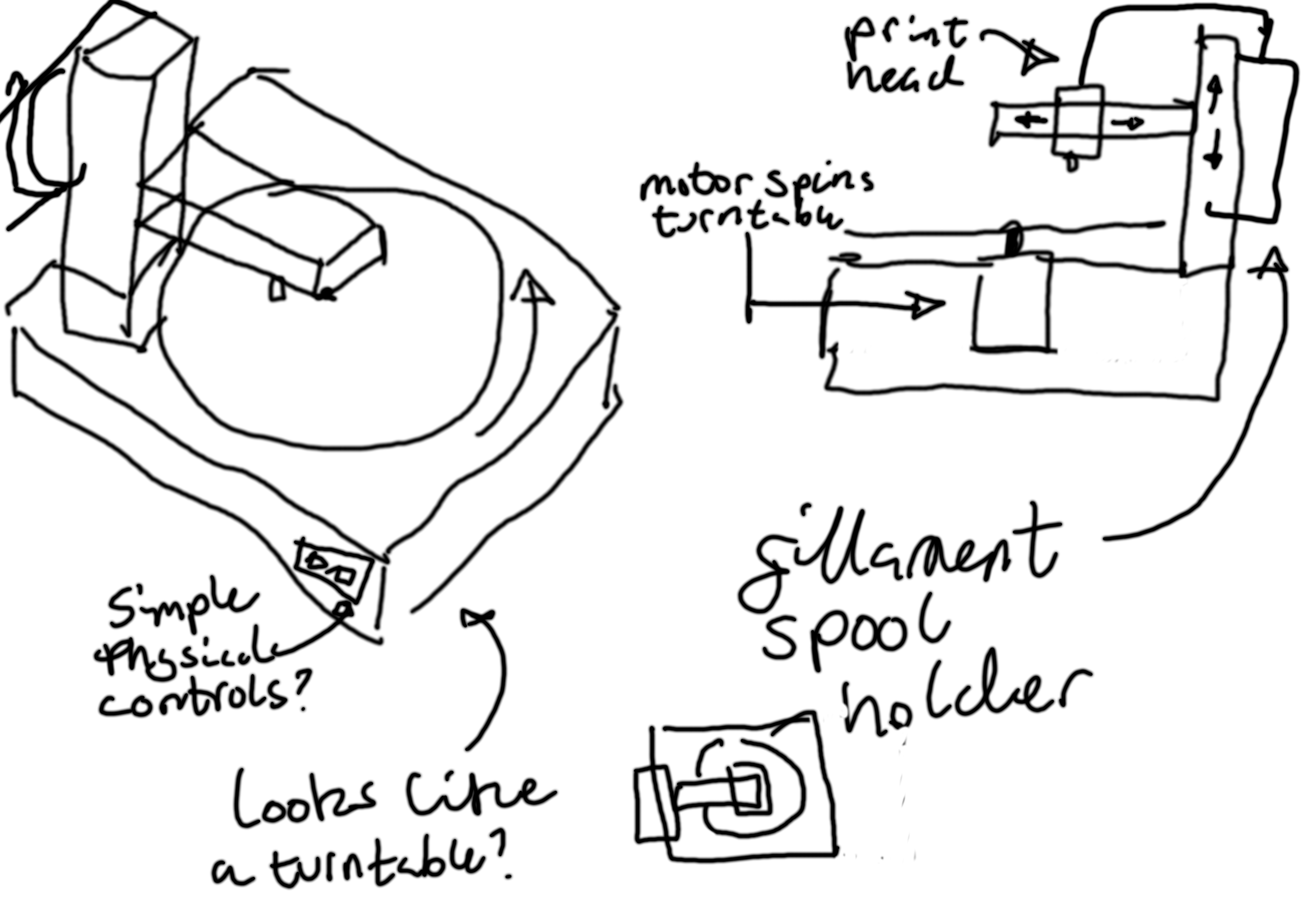
I started drawing up a design sketch for what my printer could look like using GIMP, and came up with a design I was happy with. (15 mins)
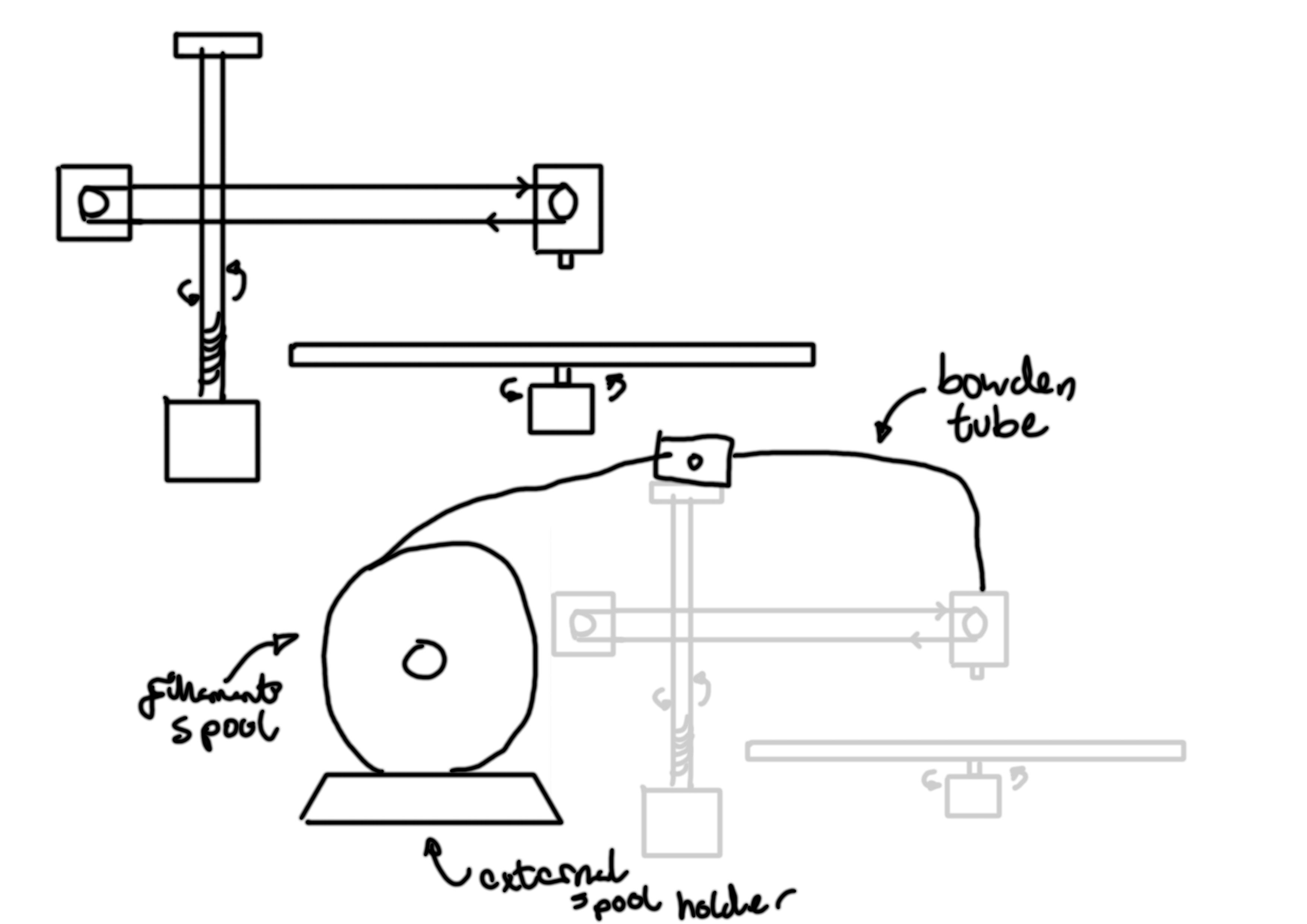
Then, I started planning out the rough mechanical design for how the printer’s motors would be positioned. (20 mins)
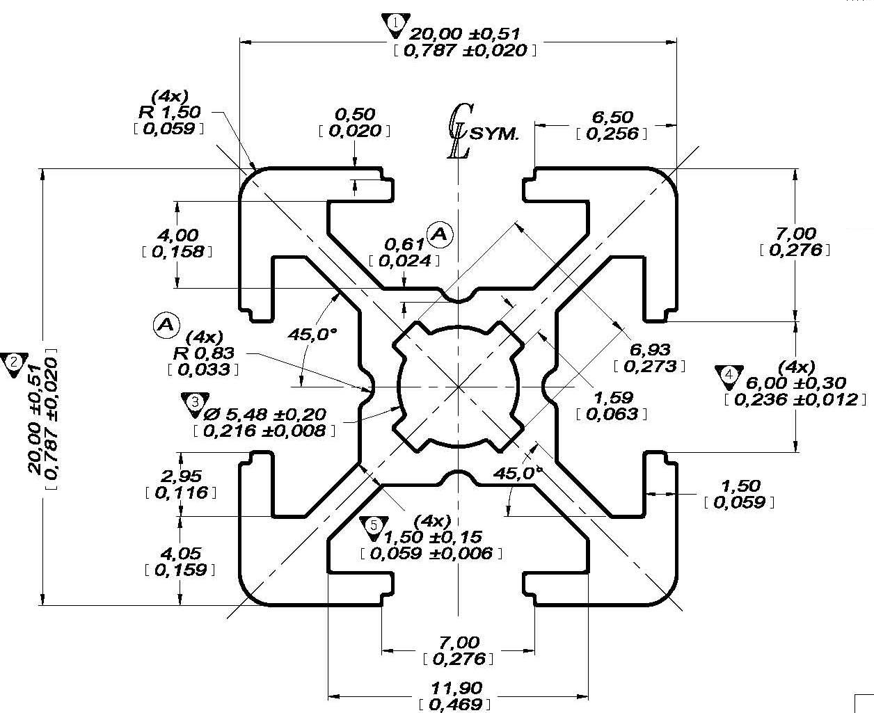
I took a few measurements from the ender 3, and did a little research, and decided on 2020 aluminium extrusion to use for the frame, and M10 threaded rod for the Z-axis. I have a feeling that these decisions might change later, but for now, that’s what I’ll use for the CAD models. I’m thinking of using FreeCAD for the printer, but I’m pretty sure I’ll regret it 😆! I also researched the time+date of the Rocky Mountain RepRap Festival to ensure I could actually make it there, without missing too much schoolwork or any exams that I’d have to do tons of catch-up for. Hopefully, if I make it, my school will allow me to take a day or two off to attend. (25 mins)
Hour 2
began on UNIX Timestamp 1739819370
I started modelling the 2020 extrusion in FreeCAD for use in my design based on this reference diagram from www.tnutz.com.
This is the end result:
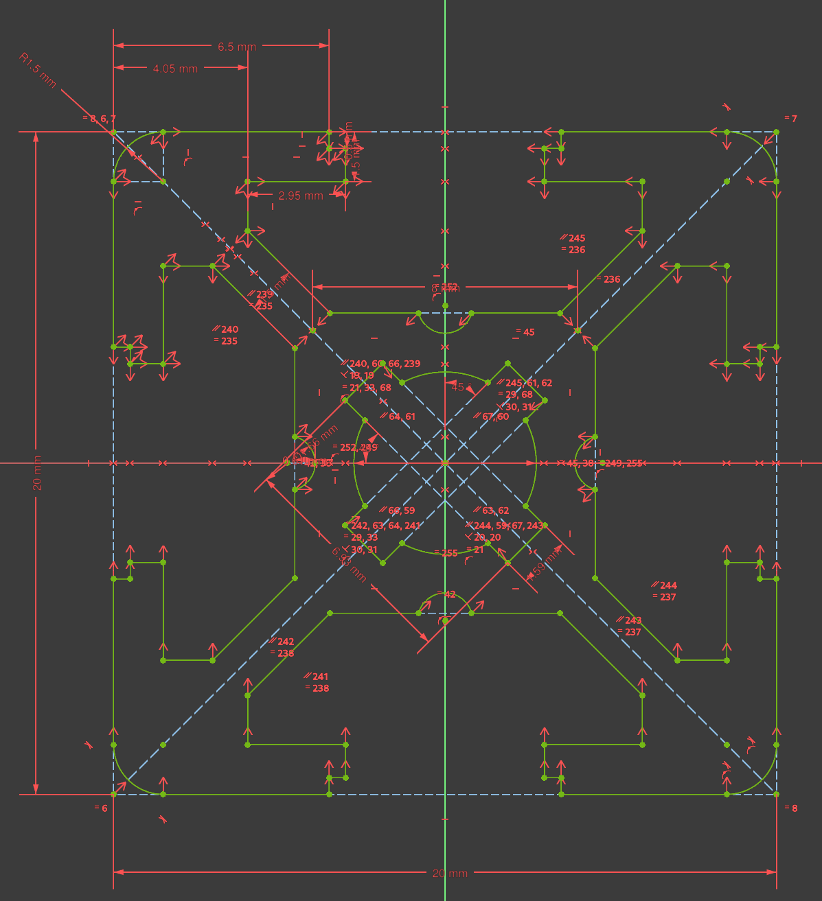
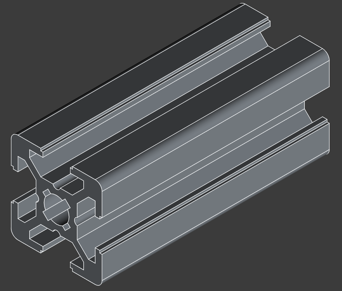
(60 mins)
Hour 3
began on UNIX Timestamp 1739885638
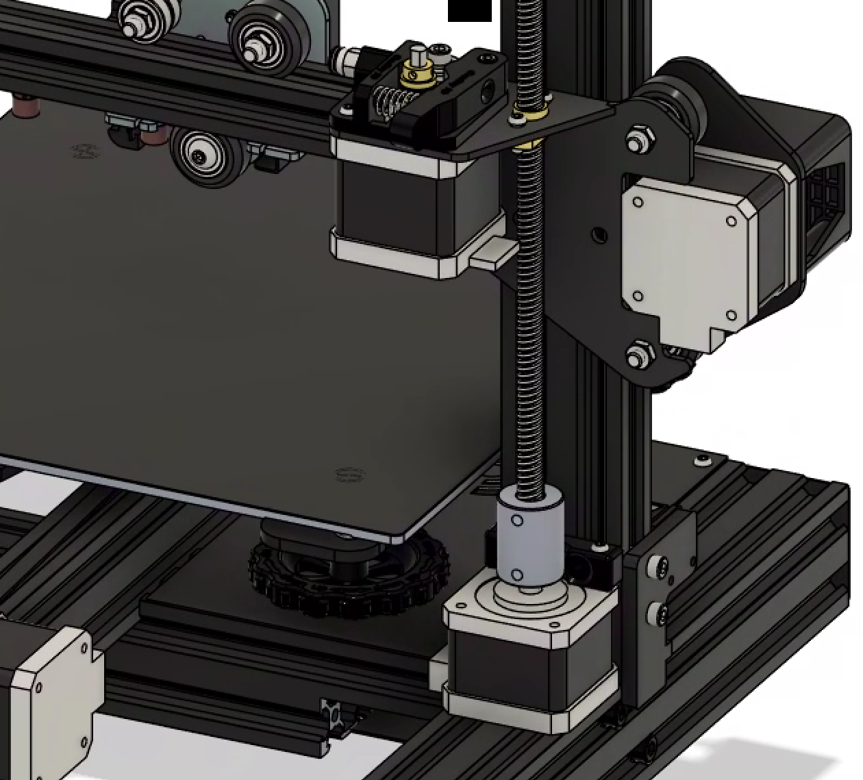
I started modelling the Z axis. I looked at the design of the Ender 3 for an example of how a Z-axis could be assembled:
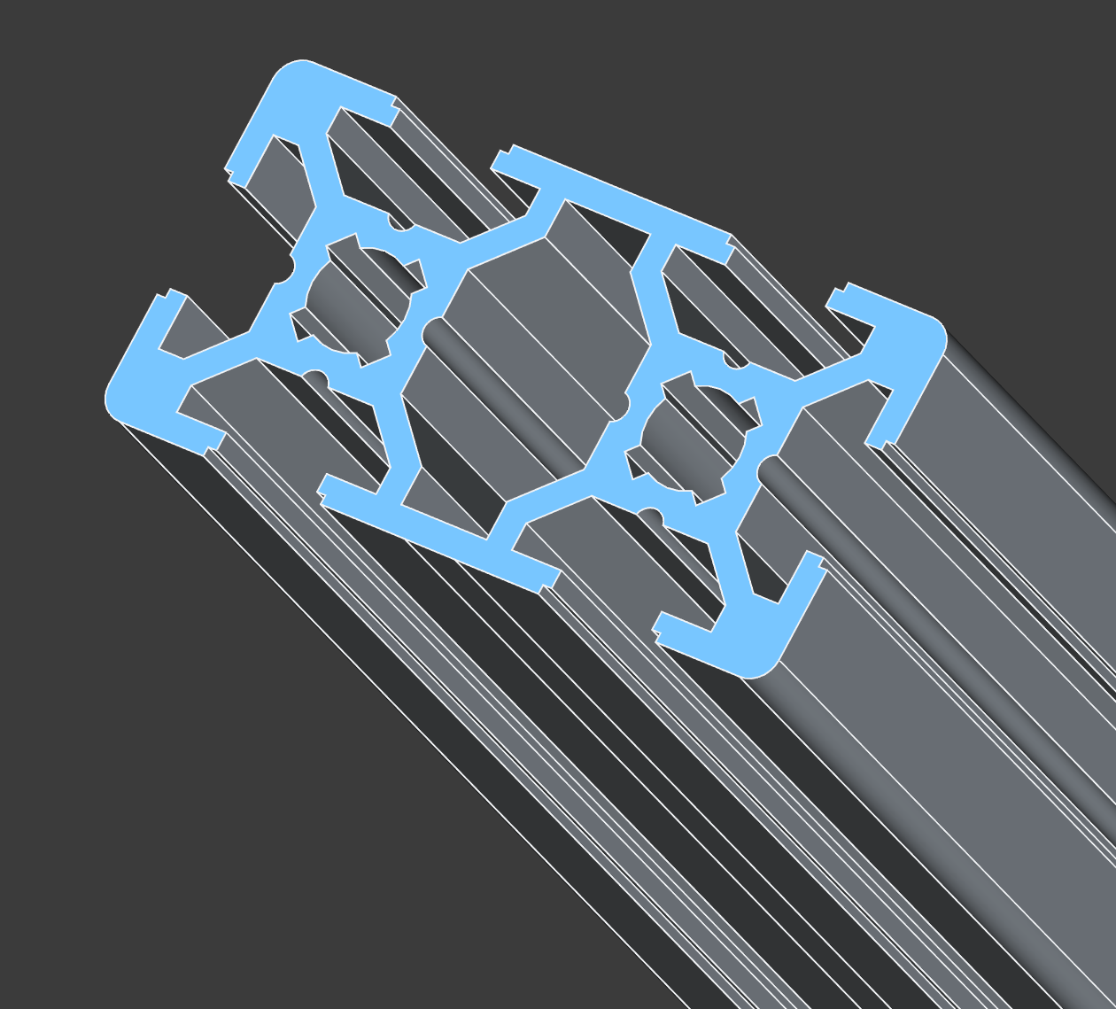
And I moddled some 2040 extrusion.
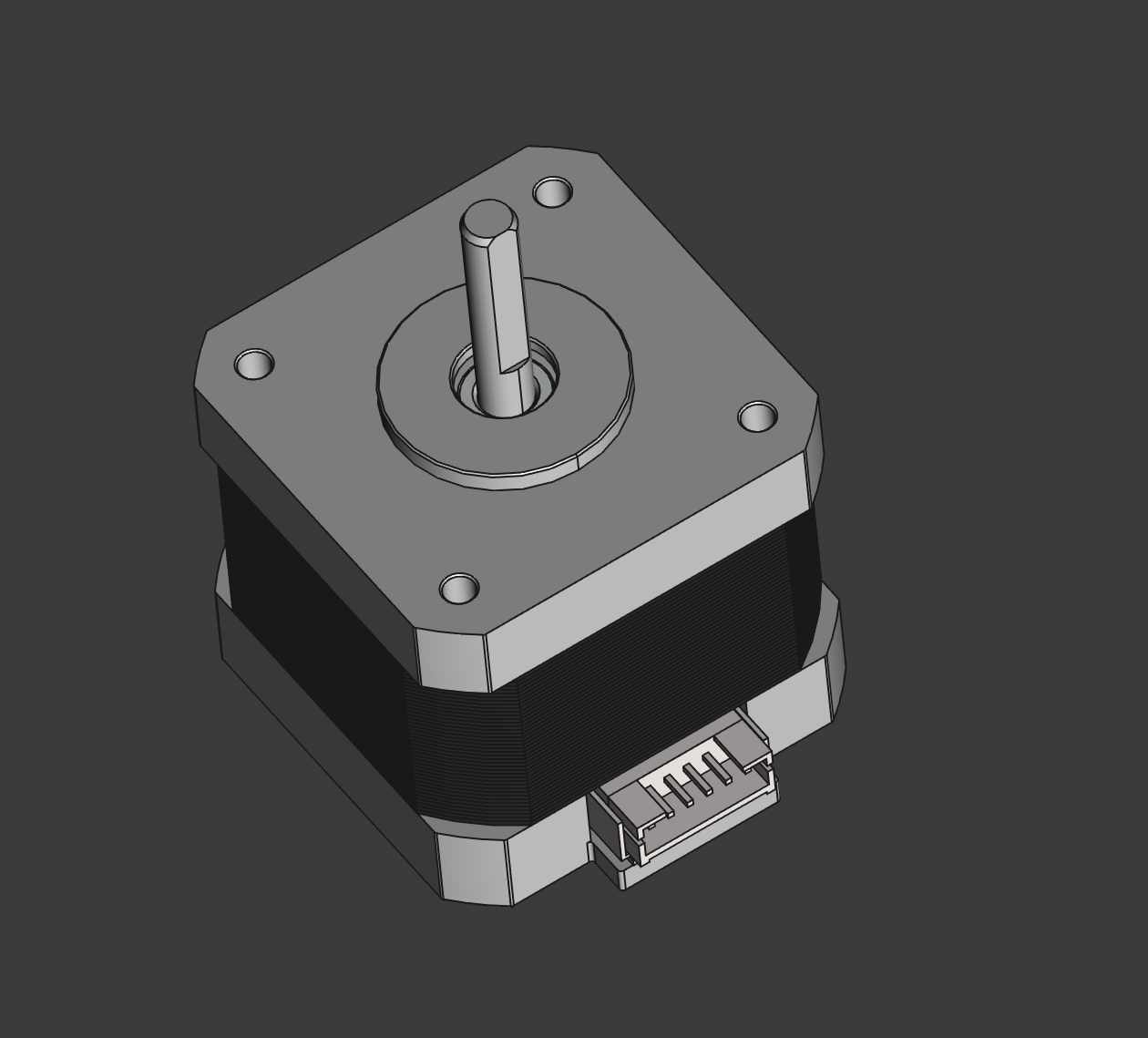
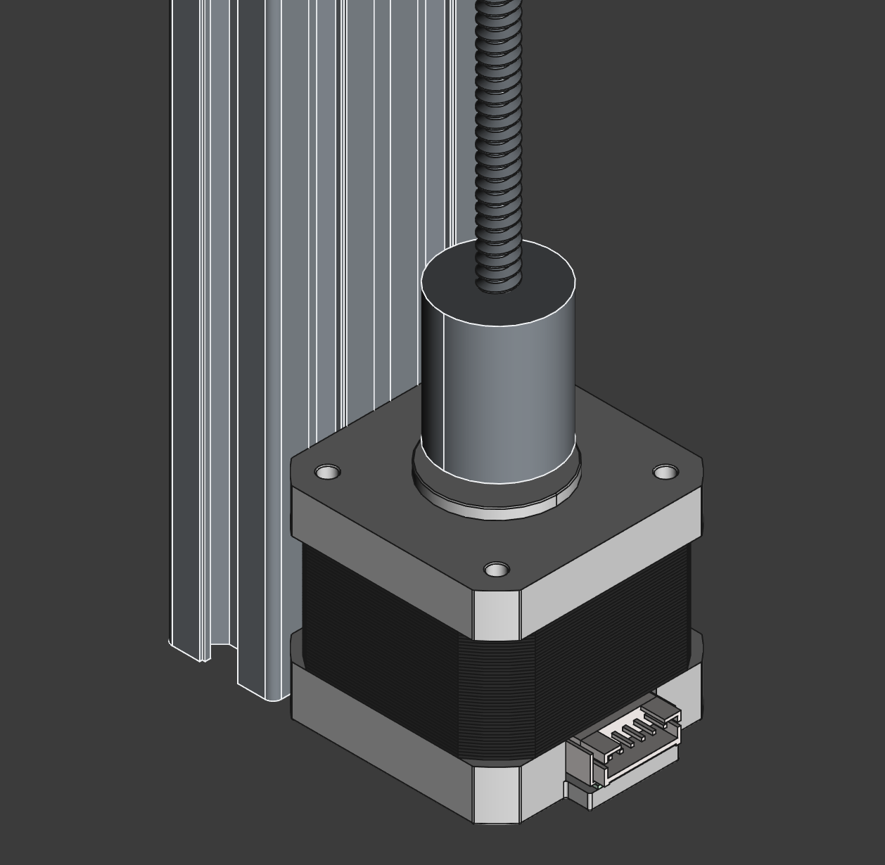
I also sourced a model for a NEMA 17 stepper motor, to use as reference for the 3D printed parts.
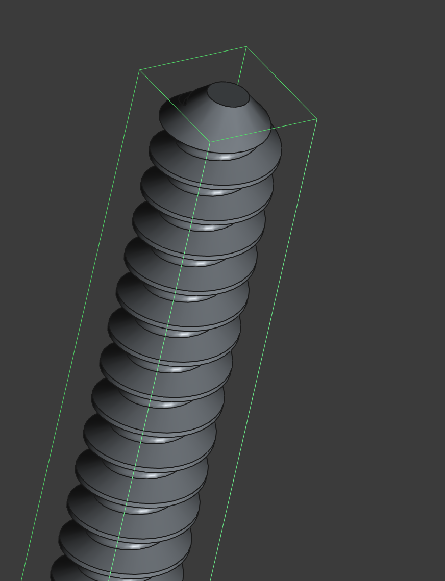
Finally, I generated a model for the threaded rod - a TR8x8 lead screw (30cm).
Hour 4
began on UNIX Timestamp 1739889914
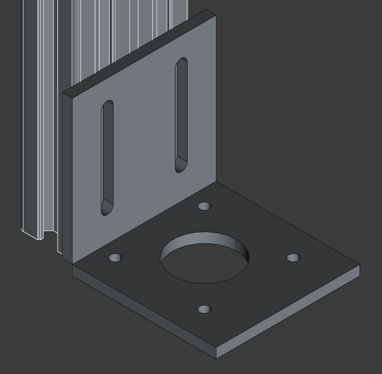
I found an existing NEMA 17 motor mounting bracket made of sheet metal, and modelled it to see if it could fit the 2040 extrusion. I spent 50 minutes creating the model, but it isn’t compatible with the 2040 rails, it just looks like it could be. Oh well! Looks like I’ll have to design a part for this bit. At least I have accurate dimensions though!
I’ve had no regrets using FreeCAD so far, the 1.0.0 version improved a lot since ~0.2. Fusion 360 would be way easier, but it’s not exactly in the ‘open source spirit’ in my opinion, because if Fusion dies, the project dies too. But FreeCAD’s code will (hopefully) be available for free, and for forever.
I’m keeping the right angle bracket model around just in case I am able to use it somewhere else, I’m getting my time’s worth out of that model someday!
I also found some brackets for attaching the extrusions together, could be worth a look at next hour.
Hour 5
began on UNIX Timestamp 1739893575
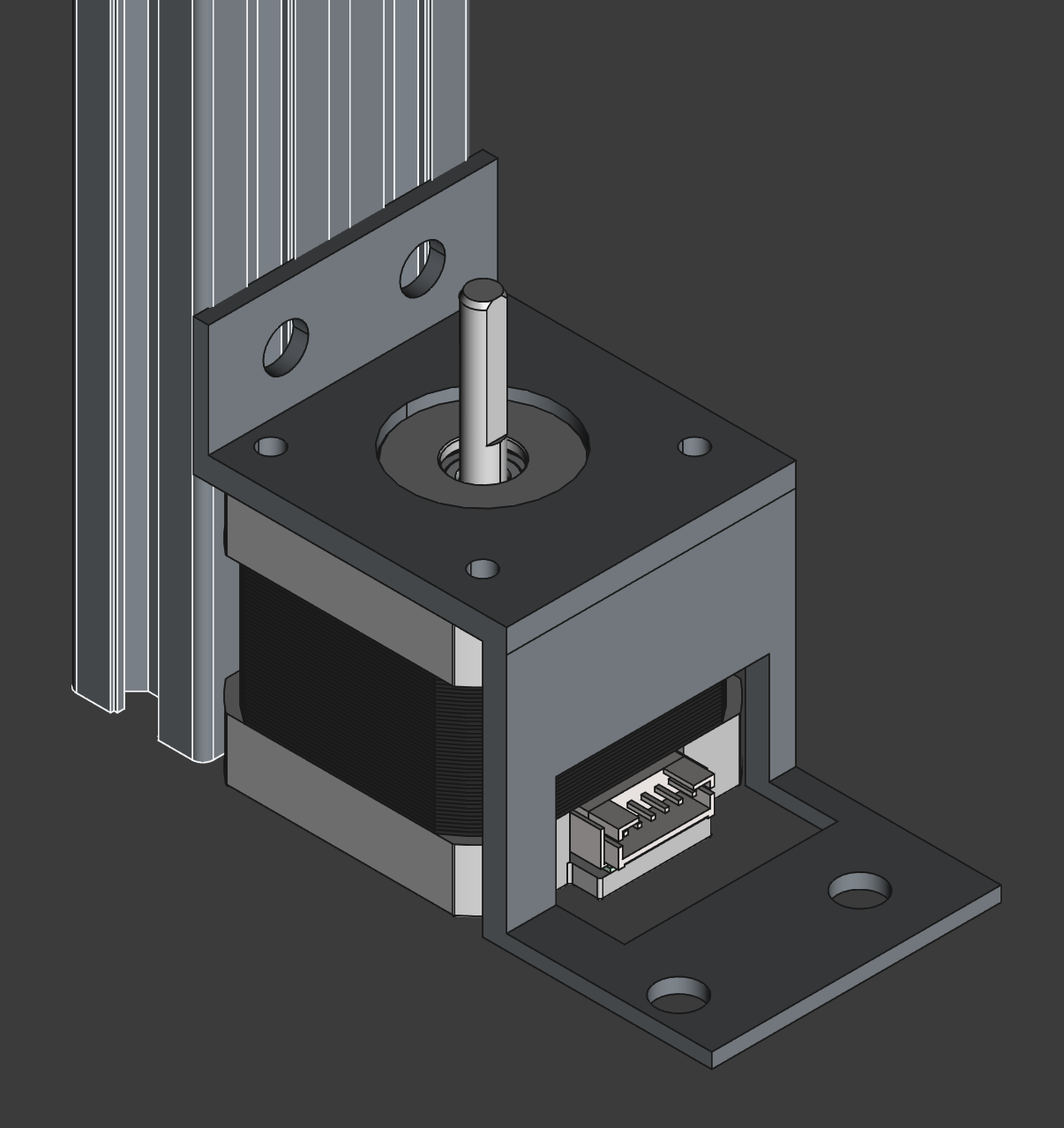
I modelled the 5-8mm shaft coupling part:
And created the first 3D-printable part, the mounting bracket for the motor.
Hour 6
began on UNIX Timestamp 1739897976
I have found the correct sizes of fasteners (nuts/bolts/TSlots) for the rails and motors that I am using, and have added them to the CAD model, in roughly the correct places, to ensure that my parts don’t overlap the heads of any of the screws I will need to install.
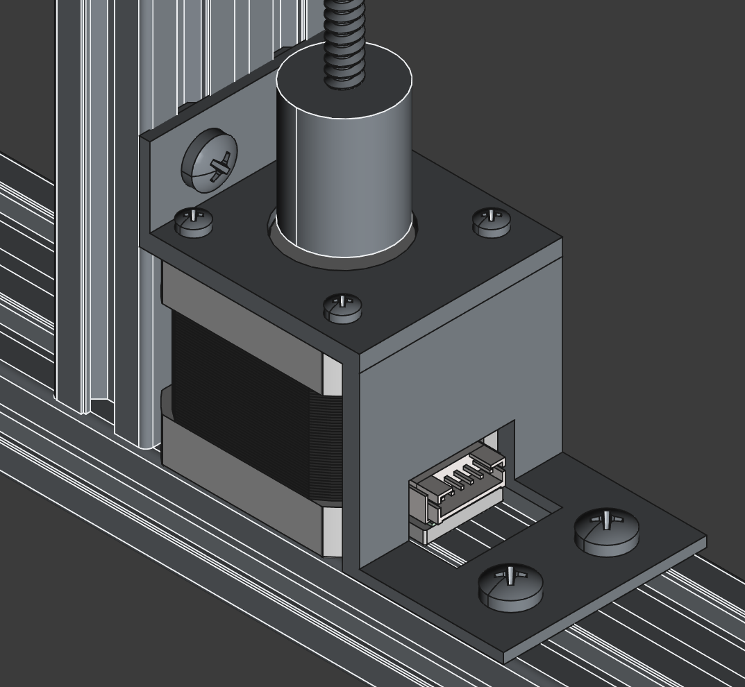
Finally, I renamed all of the parts to have (mostly) sensible names:
Hours 7-9
hour 7 began on approx. UNIX Timestamp 1740168000 and 8-9 on approx. UNIX Timestamp 1740256200
I have made quite a lot of undocumented progress on-and-off through short sessions in my free time, so in summary the changes are:
- Added a trapezoidal nut to follow the lead screw
- Switched to using hex bolts instead of phillips screws
- Set the position of objects manually, to avoid imprecision from visual only alignment
- Found a pulley for the X axis belt, and a similar-enough model
- Built a carriage to follow the nut by holding the nut using screws screwing into heat-set inserts
Hour 10
began on UNIX Timestamp 1740416875
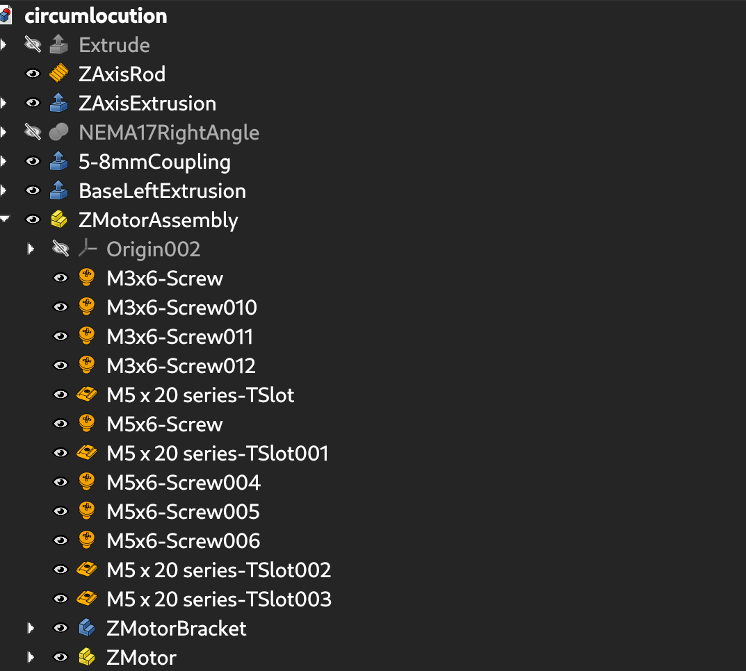
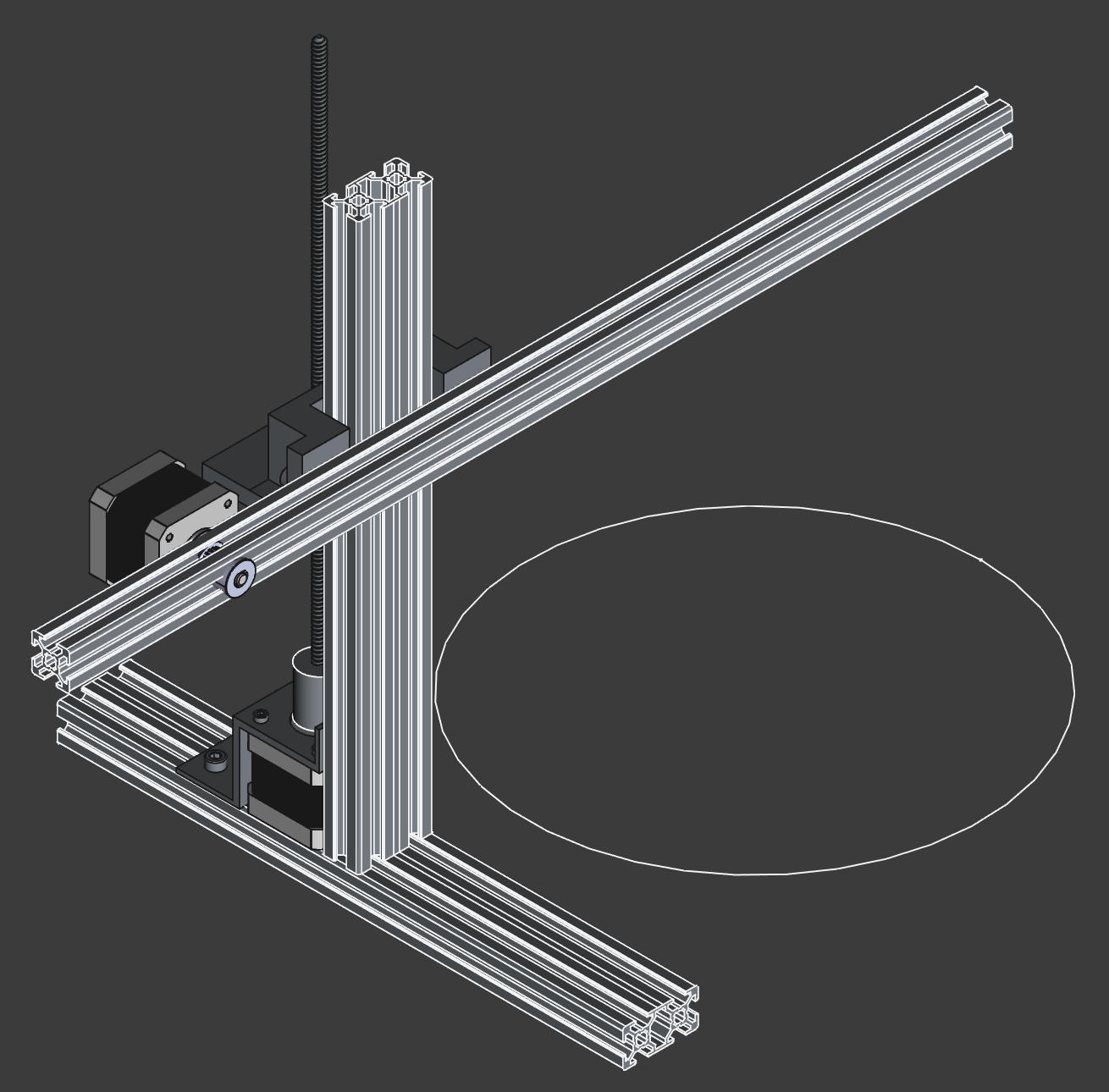
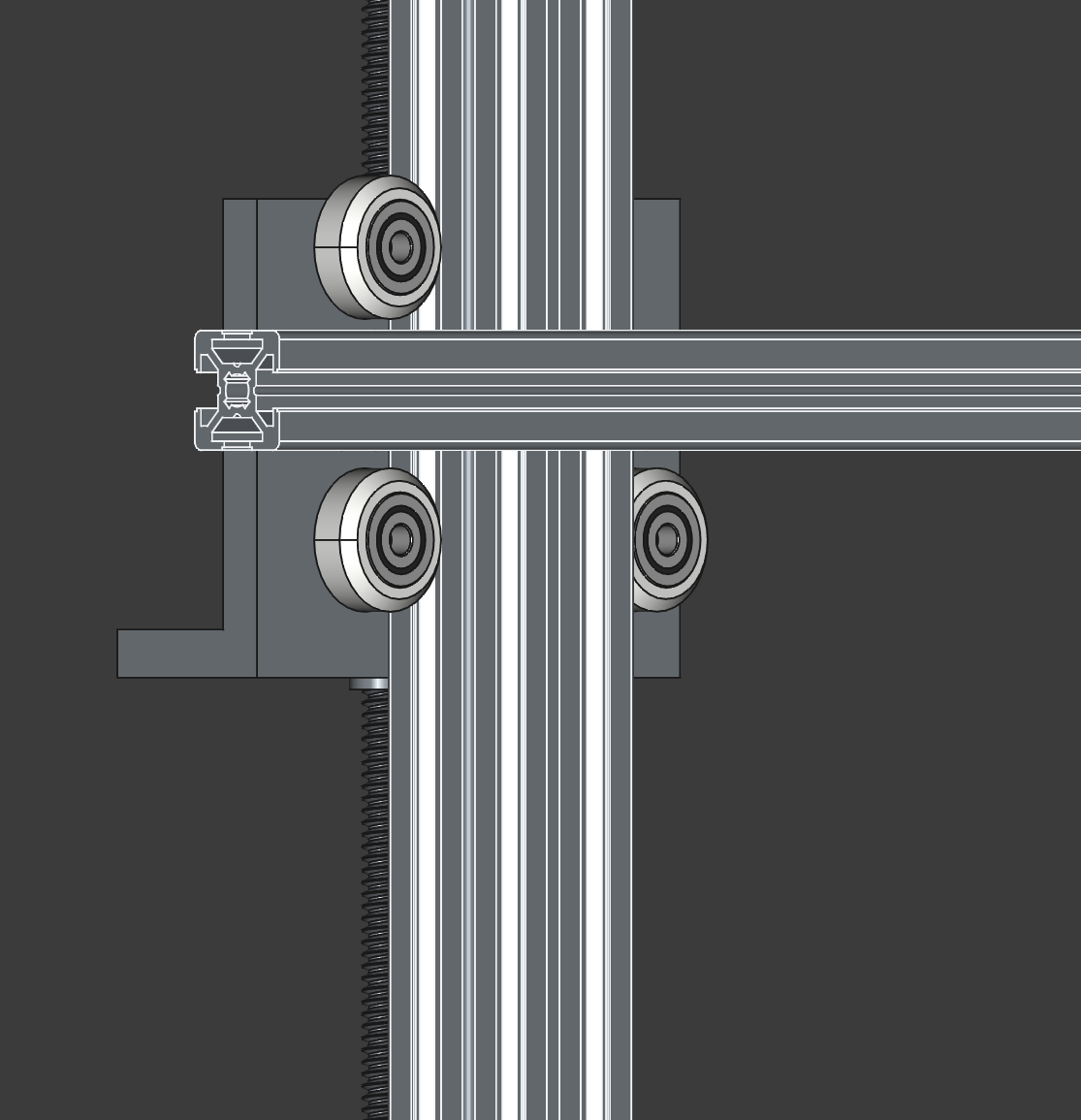
I planned out the position for the rollers to follow the Z axis:
Added the rollers, and started re-building the carriage.
Hours 11-16
took place across multiple days between timestamps 1740416875 and 1741539544
I re-built the entire Z-following carriage into two 3D-printable parts, held together with insertable nuts and screws.
(as seen from front side)

(as seen from back side)

Hours 17-20
took place across multiple days between timestamps 1741539544 and 1742252892
I moddled a holder to keep the X motor in place, added a belt and coupler, and connected the end of the extrusion to the X motor holder with an M6 screw to prevent the X rail from sliding through the Z follower.

Hours 21-50
took place across the months of March and April 2025, hour count estimated - unknown
I accidently finished most of the printer without writing a single journal entry. (oops!)
I also just came up with the tagline to sum up this whole experience so far:
Welcome to maker hell, where we have all the parts of a broken Ender 3 clone, none of the time, a copy of FreeCAD, and an unhinged desire to watch a 3D printer spin.
I think it really captures the feeling of ‘what do I do now?’ after just disassembling a printer into parts, and realising you have to CAD it all back together into a functional design.
Most choices made during the design process were based on what I had lying around from my old printer (the Sovol SV01), what was availiable on AliExpress, and what was easiest to 3D model.
Considering this is my first ‘real’ CAD project, I’d say I did an OK job. Perhaps if I was to redesign it, I’d use linear rails, or various better options than the old parts of a broken printer. It would’ve opened me up to making a better, more unique, and more functional design, but would’ve cost significantly more. Maybe once I’ve finished building it I’ll re-assemble the parts back into the Ender 3 clone it used to be. We’ll see.
The due date of the design was March 31st, but I overran into April 7th, finishing a few hours before last call.
I don’t have high hopes for this project.
