EOS 3D
EOS 3D
This document tracks progress for the YSWS portion of this project. It also serves as a journal documenting the development process.
Preface
Before starting this project, I must outline the key requirements to ensure clear project direction and successful execution. I initially came up with the following requirements:
- $300 (USD) budget
- Klipper compatibility
- No calibration printing is required
- 180x180mm build space
- Cantilever structure
- CFD-optimized part cooling
- Safety considerations:
- Must not pose a fire hazard
- Must not cause harm to the user
- PicoMMU compatibility
Although I have extensive experience working with 3D printers, this is my first time designing one. Through this process, I aim to deepen my understanding of 3D printer mechanics, refine my CAD skills, and improve my approach to mechanical design. Additionally, thanks to Hack Club, this project offers the added benefit of a free printer.
The name of this project, EOS 3D, is inspired by the Greek goddess of dawn, Eos. Dawn symbolizes new beginnings, reflecting a personal milestone in my projects and an entry point for tinkerers.
Day 1 (February 1st, 2025)
Hours worked: 8
Total hours on project: 8
BOM Selection
Creating the Bill of Materials (BOM) required balancing cost-effectiveness with performance and safety. While selecting parts, I took into account the following:
- A budget hotend from a reputable brand to ensure safety and good flow.
- A reliable direct-drive extruder.
- The Cartographer probe for its high-resolution bed meshing capabilities and automatic Z-offset calibration via Carto Survey.
- BTT SKR Mini and a Raspberry PI for its cost-effective control.
- A cheap heated bed with a PEI spring steel sheet.
- A PSU with a large overhead from a reputable brand.
Compiling and refining the BOM took approximately four hours.
Toolhead Development
With the BOM completed, I decided to tackle the printer’s tool head first, as it serves as an “anchor point” for the build.
I began by modelling the X-axis rods and bearings to establish clearance constraints between the toolhead and the rods.
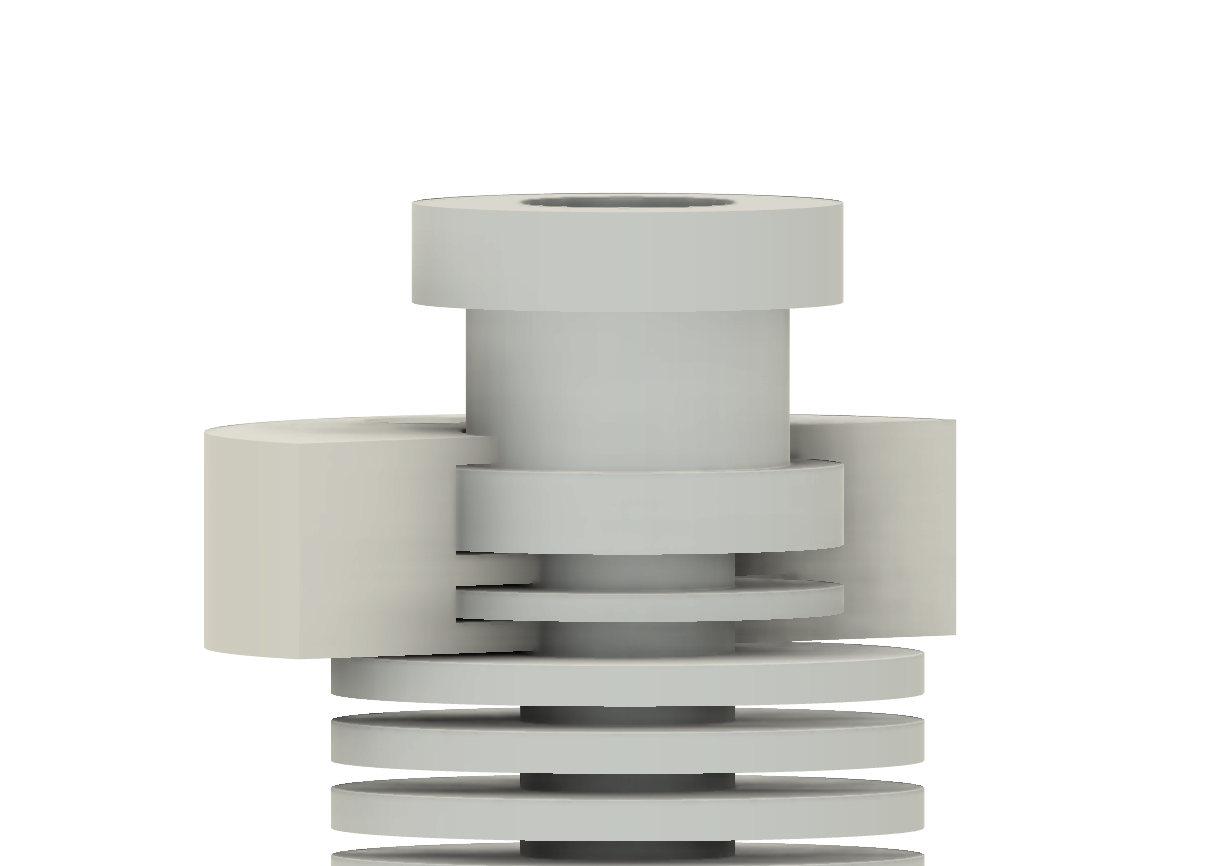
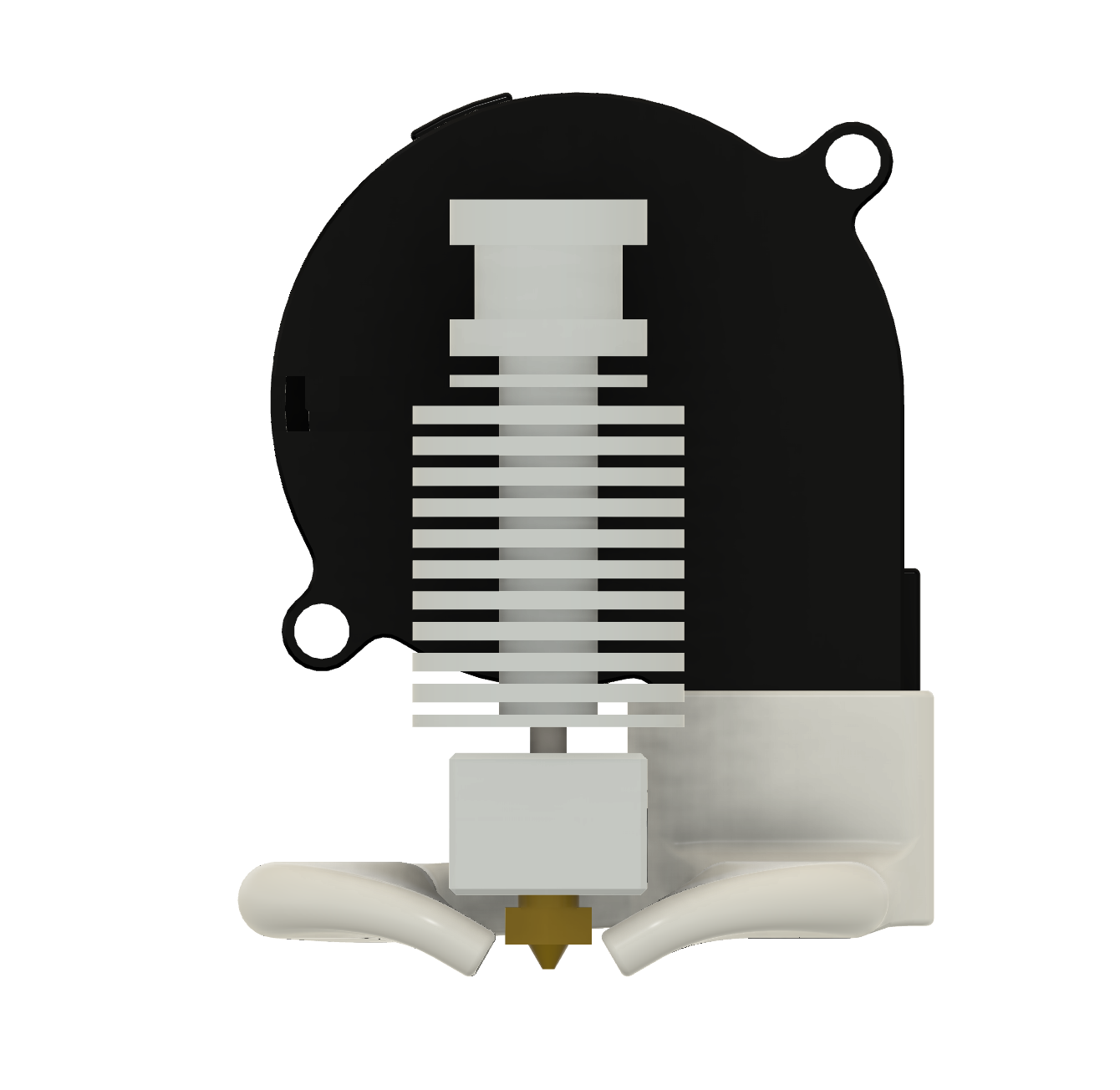
Next, I imported the CAD models for the Sherpa Mini extruder and the E3D V6 hotend, then started designing a mounting solution. I opted for a clamping mechanism for the hotend, as shown in the image below:
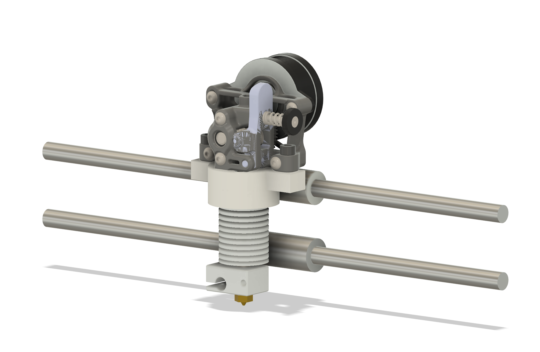
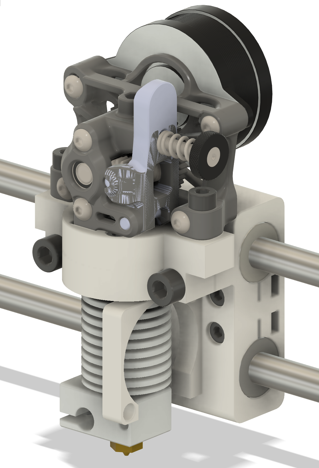
By the end of the day, I refined the mounting system and securely integrated the Sherpa Mini with the mount. Below is the final design on day 1 (ignore the mesh issues on the Sherpa; those were present in the CAD model):
Day 2 (February 2nd, 2025)
Hours worked: 2
Total hours on project: 10
Further Toolhead Development
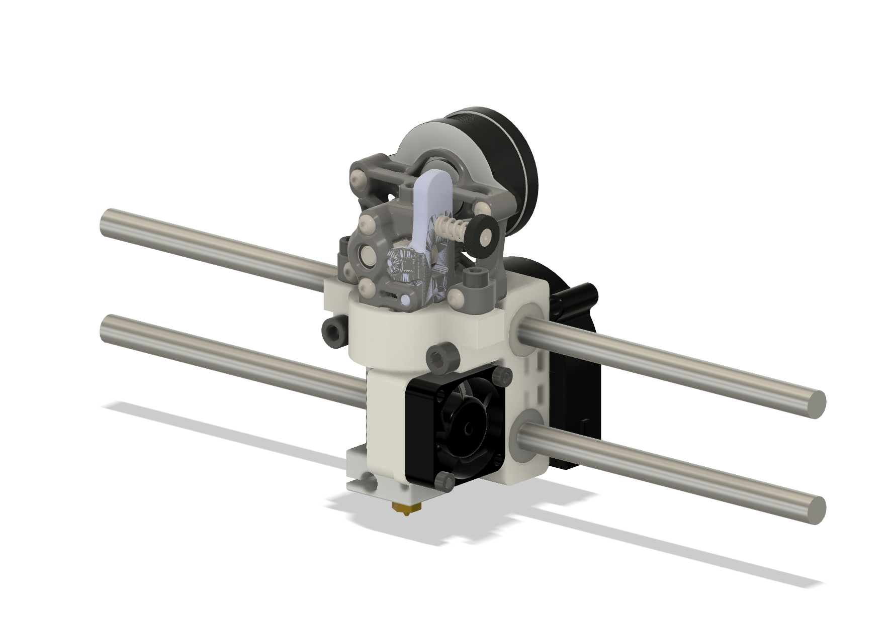
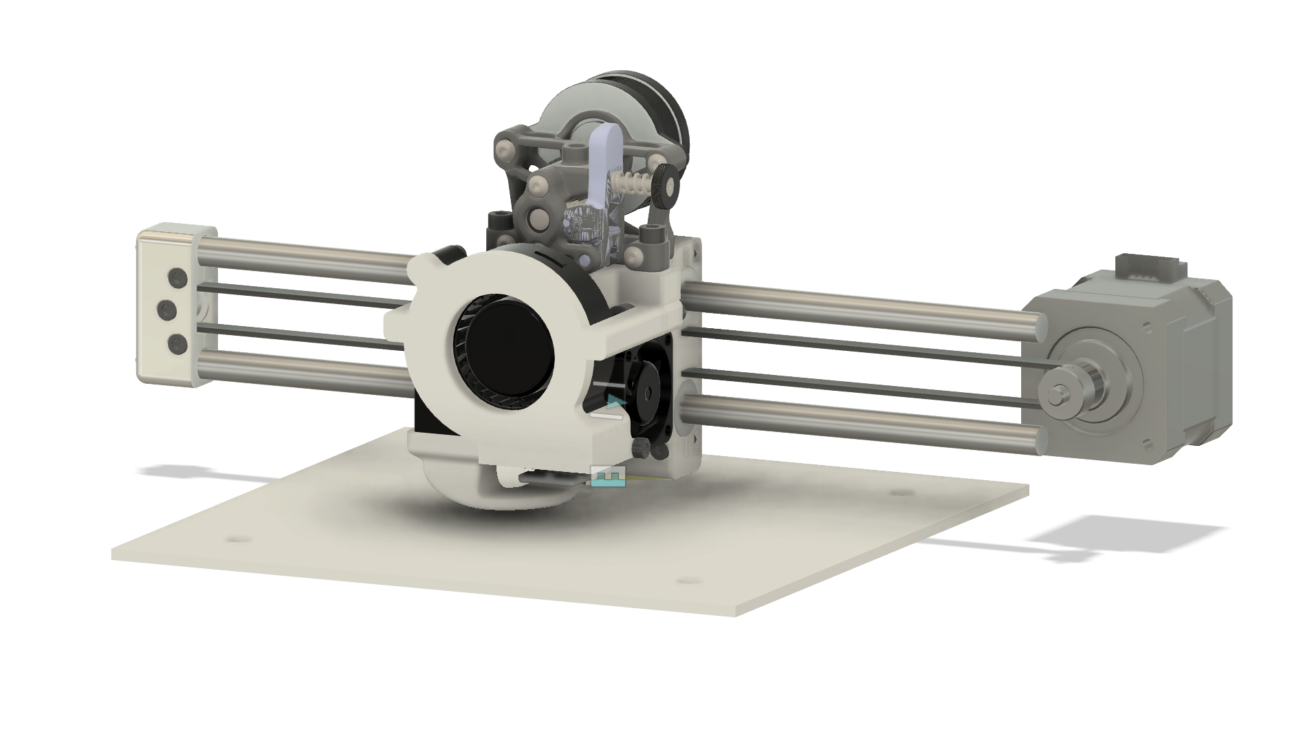
Today, I completed the connection of the toolhead to the linear bearings with inspiration from the Prusa Mini. I began modeling the cooling fan duct but encountered challenges in designing one that is both functional and aesthetically pleasing.
Here is the final model of the day:
Day 3 (February 3rd, 2025)
Hours worked: 1
Total hours on project: 11
Fan Development
Today, I did minimal work; however, I finished and placed the part cooling fan. Tomorrow, I will begin designing it and running CFD tests.
Day 4 & 5 (February 5th-6th, 2025)
Hours worked: 4
Total hours on project: 15
First Fan Iteration Completed
After extensive trial and error, I have an initial design for the fan duct. The goal was to implement a dual exhaust setup, which presents more challenges but should enable more even cooling across the print.
Next Steps Before CFD Analysis:
- Raise the outlets so they are positioned above the nozzle.
- Adjust the outlet angles to prevent airflow from hitting the nozzle.
- Increase clearance to the hotend to prevent outlet deformation
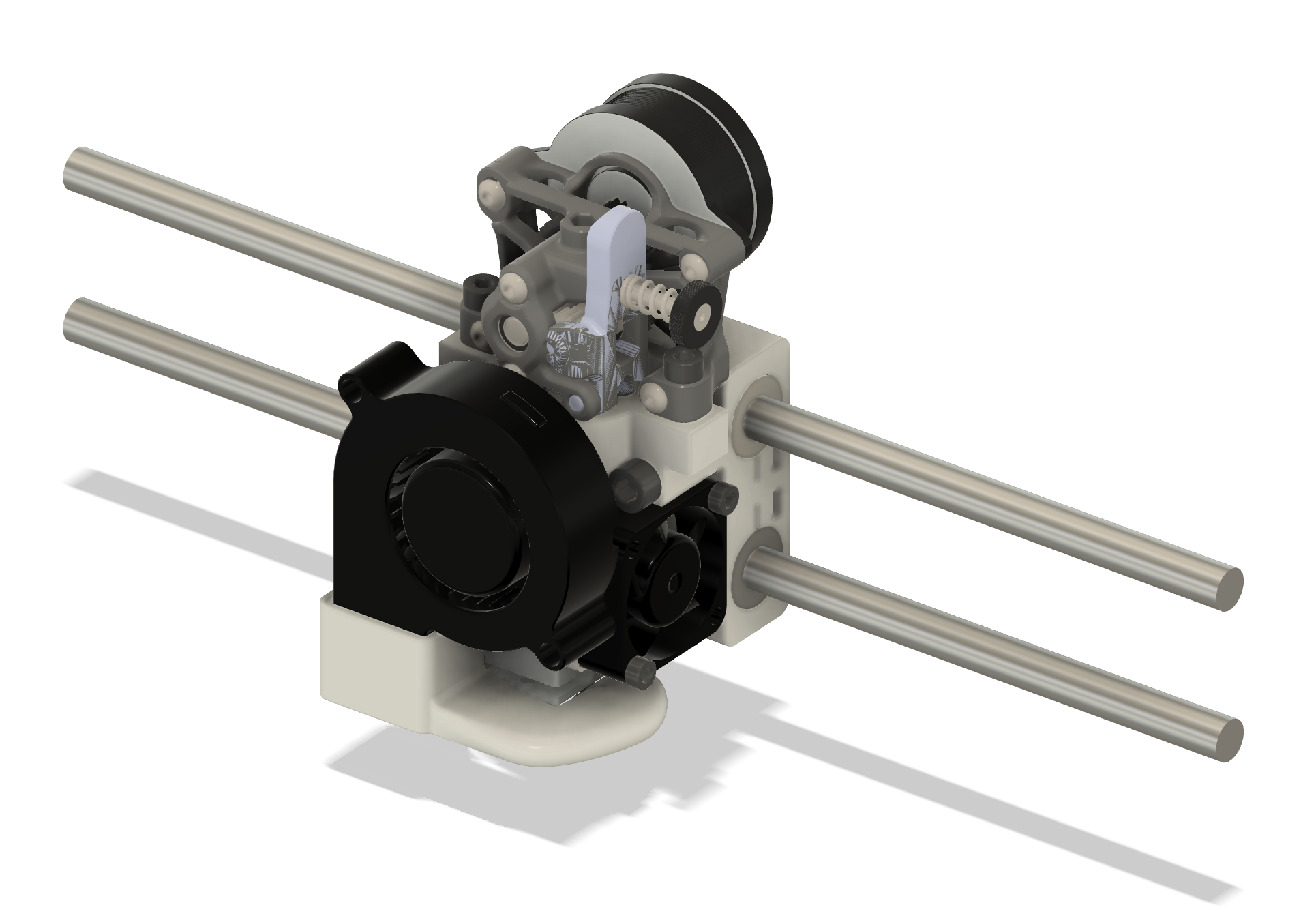
With these changes, I plan to start optimizing the design tomorrow before running CFD simulations. Below are images of the fan duct (rear view) and the complete model in its current form.
Day 6 (February 7th, 2025)
Hours worked: 5
Total hours on project: 20
Computational Fluid Dynamics
With the latest changes in place, it was finally time to put the design through CFD analysis. Having never used CFD software before, I knew this would be a challenging process.
I initially tried Autodesk CFD and ANSYS Workbench, but getting them to work felt overwhelming. Eventually, I discovered SimScale, which turned out to super user-friendly. I followed this YouTube tutorial to set everything up.
After a long computation wait, I finally got to see the airflow results—and they were really bad. Not entirely surprising for an initial design, but definitely something to improve. The results are shown below:
Tomorrow, I’ll begin optimizing the design and rerun the CFD analysis to see how much improvement can be made.
Day 7 (February 8th, 2025)
Hours worked: 6
Total hours on project: 26
Finishing the Part Cooling Duct
After reflecting on yesterday’s analysis, I decided to try a different ducting style to improve overall airflow. This new design features a 180° duct, which I hoped would distribute air more evenly. I started by sketching the outlet, connecting it to the rest of the duct, and running it through CFD. After setting everything up, I obtained the following result:
CFD Run 1


As shown in the results, the airflow was heavily biased to the left, causing a lack of airflow through the right slit and the exit airflow being angled.
For the next iteration, I attempted to make the turn more gradual to prevent the airflow from favoring the left.
CFD Run 2


The results looked good! However, there were still three issues:
- The airflow was still left-biased.
- There was a lot of extra space (look at the top left and bottom right of the ducts).
- There was no airflow through the rightmost duct when there was no object “printing,” as shown below. This is the big one.

For the next run, I made some adjustments to the ducting to make it more smooth and prevent the sharp corner. I also made the throat leading up to the outlet smaller and added a fillet to the outermost outlets.
CFD Run 3


With the throat being tighter, I was hoping for the air to be forced into the right side; however, this was not the case.
I then made the interior of the outlet slightly smaller horizontally so there was less open space and made some adjustments to the ducting leading up to the outlet.
CFD Run 4


These changes were a big step forward in resolving the overall bias issue. There was still some airflow lacking on the right side; however, the airflow was less skewed.
For the next run, I added a barrier down the middle to help balance the airflow between the two halves.
CFD Run 5


Adding the barrier finally solved the issue, and there is really nice flow. It pretty much goes straight down the middle, and each slit is getting sufficient airflow. I decided this was good enough and moved on.
The only thing I would really change is the angle of the slits, but this design is sufficient and looks nicer.
Post CFD
With the part cooling fan optimized, I quickly designed a mount for everything and called it a night.
Note
Before I end this journal entry, I want to mention that I did use AI (specifically ChatGPT) to assist me in optimizing the design. I have no formal education in this space and no mentors to help me out, so using AI was my best bet.
Tomorrow, I will be finishing off the toolhead with the mount for the Cartographer and PicoMMU “Hub.”

Day 8 (February 10th, 2025)
Hours worked: 2
Total hours on project: 28
Finishing the toolhead
Today, I modified the part cooling fan mount to improve its aesthetics and structural integrity. I also installed the Cartographer probe using a simple mount. Tomorrow, I will begin working on the X-axis!
Note: The PicoMMU infrastructure will be added after the initial prototype is completed.

Day 9, 10, & 11 (February 11th-13th)
Hours worked: 5
Total hours on project: 33
Begin the X axis
Over the past few days, I implemented the belting for the X-axis using a clamping system that secures the belt with a screw. The endplate design is based on the Prusa Mini, as it was the simplest solution after testing other strategies.
Day 12 & 13 (February 14th-15th)
Hours worked: 2
Total hours on project: 35
Z Axis Work
I have been working on the mounts and positioning of the Z-axis. Due to the simplicity of the design, not much work was required.
Day 14, 15, 16 (February 16th-19th)
Hours worked: 5
Total hours on project: 40
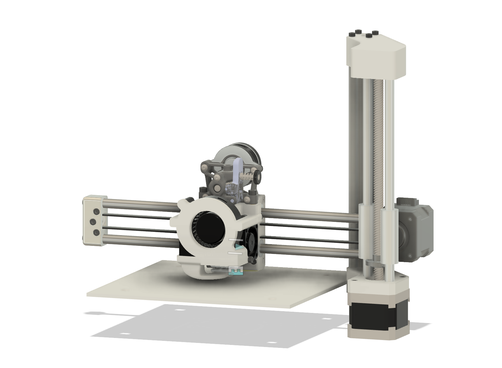
Finish Z Axis
Over day 14, 15, and the start of day 16, I finished the Z axis. This means I will be starting the last axis of the project, the Y axis.
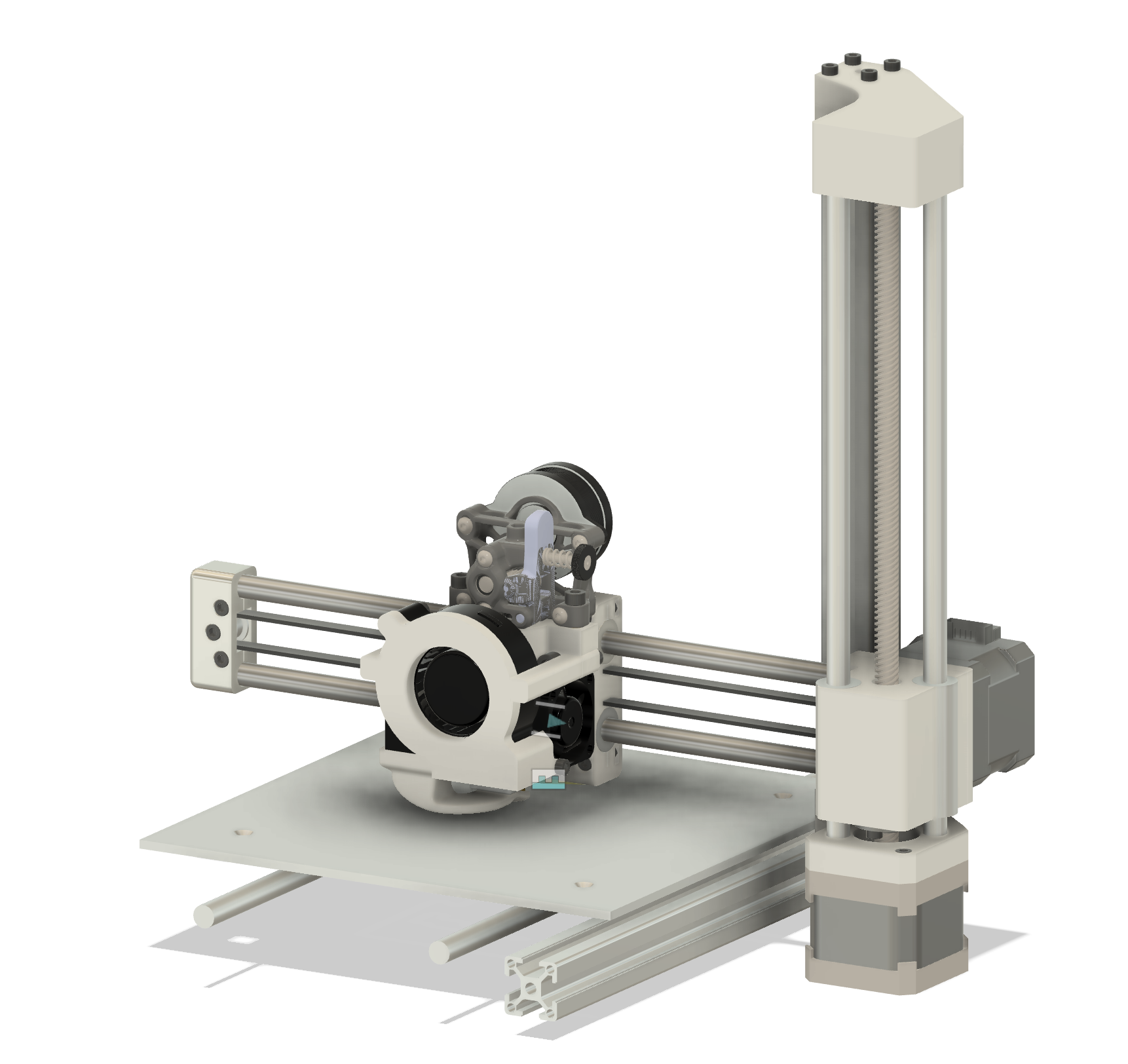
Start Y Axis
On day 16, I started the Y axis. As of now, I have the extrusion, rails, and carriage designed. The carriage will be 3D printed with the CarbonX PA12-CF. It is an expensive filament; however, it has a very high Tg (150°C) compared to Bambulab PAHT-CF and Polymaker’s counterpart (both are around 70°C).
Tomorrow, I will design the endplates for the rails and extrusion, the mount holding the carriage to the bearings, and the belting.
Other than that, I just have to design the mounts for the electronics (motherboard, RPi, and power supply), and I’m done!
Day 17, 18 (February 20th-21st)
Hours worked: 6
Total hours on project: 46
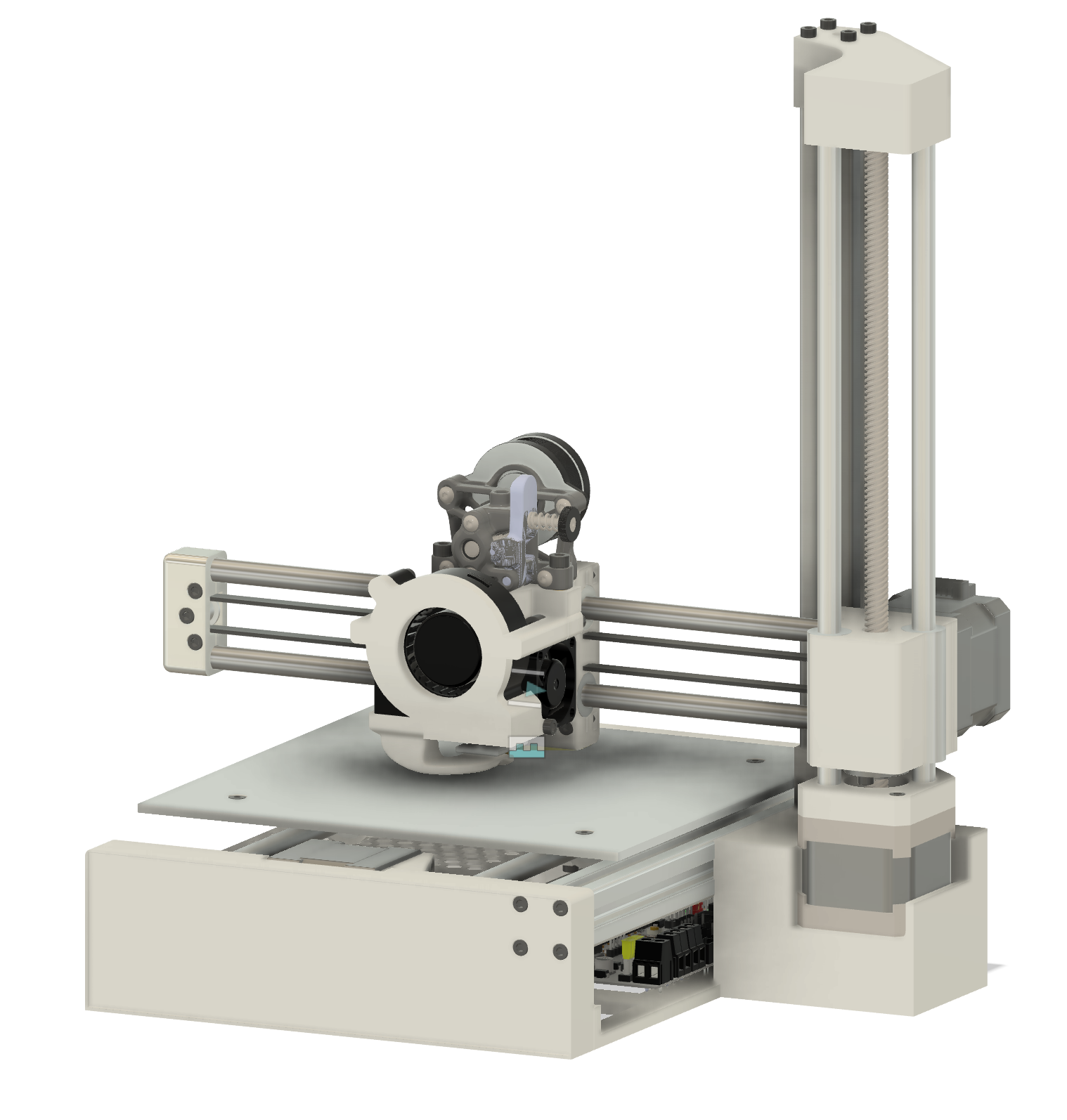
Finish the printer!
I have been slacking a little bit on the journal while finishing the printer off. Anyways, its done! I don’t have much to say but it was just a lot of fitting things together and basic problem solving. I will be revising the BOM tomorrow to add some things that have changed.
Soon, I will order the parts, print the printed parts and start building!
Day 19, 20 (February 23rd-24th)
Hours worked: 3
Total hours on project: 49
Ordering the Parts
With the printer completed, I successfully received my grant! Before placing orders, I had to swap out several parts due to availability issues. I then ordered the Carto probe and Raspberry Pi Zero from their respective websites. However, I encountered payment issues on AliExpress, as my card was being declined. After several attempts and troubleshooting, I finally managed to place the order successfully. Now, all that’s left is to wait for the parts to arrive and finish printing all the necessary components!
Colouring the Printed Parts
I want my printer to be black with green accents, so I painted some selected parts green for contrast. Additionally, I created a 3MF file to easily reproduce the design in the future.
The images for this day were lost :(
Day 21, 22, 23 (March 7th-9th)
Hours worked: 10
Total hours on project: 59
Parts came in!
I have received all but one part. This means I can get building! Before printing, I tested all the electronic parts to make sure they were working. Luckily they all were working as advertised so I began printing!
PSU Changes
Before printing, I realized the PSU was much bigger than the CAD model I initially chose. Therefore, I had to make some changes to the bumper to compensate for this change.
Hotend Changes
I made some slight changes to some of the hotend assembly to improve printability and a few fixes.
I’m hoping to be able to start building everything tomorrow morning!
TODO
- Add back all the fasteners lost with the changes

Day 24, 25 (March 21st-22nd)
Hours worked: 6
Total hours on project: 65
Making adjustments
After the initial printing of the parts, I had to make adjustments for fitment, among other issues. These included adjusting the PSU mounts, adjusting the mounting to aluminum extrusions (I thought they had screw holes threaded) and the part cooling fan.
Part cooling fan
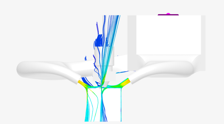
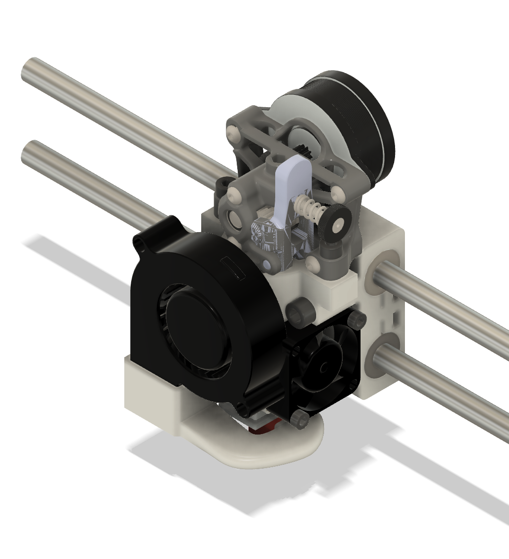
The old design was not fitting well due to a screw on the heatblock I did not account for. Instead of struggling to change it, I decided to completly redesign the part cooling fan duct. It now uses a single flat nozzle. After running CFD, the airflow is just as good as the original design with the added bonus of being a lot less complicated. Below is the CFD analysis and the duct itself:


Final remarks
Firstly, I just want to give an update on why there was a two week break. I was on vacation and could not work on the project. Secondly, I plan on adding the PicoMMU integration (really just a filament cutter and mount for the 4-1 bowden hub) once I have the printer up and running. I still have to add back all the fasteners. Its a PITA to do and I plan on doing it all in one go once the design in finalized.

Day 26, 27, 28 (March 24th-27th)
Hours worked: 5
Total hours on project: 70
X-axis Issues
After assembling the X-axis, I noticed that it could twist, which is obviously not ideal. Despite strengthening the area and tightening the rod fitment, the problem persisted. It wasn’t until I discovered that the rods were not fully inserted that I was able to resolve the issue.
Final Assembly
I made a few minor modifications to some components, and the axis is finally complete! Below is an overview of the physical build:

