Meteoroid
modified: 2025-04-02T23:19:20-06:00
Made by: @techy-robot
Repository link: https://github.com/techy-robot/Meteoroid
Total hours so far: 98.5 hrs
- I have a 3D printer or will be getting one before March 21st
Overview
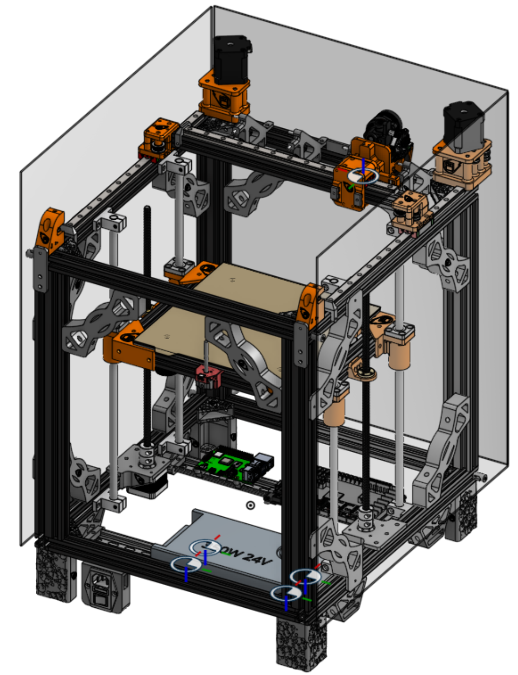
Production-ready 3d printer based on a Ender 5 frame, with multifunction tool changing, bed changing, and accessories with robots. https://github.com/techy-robot/Meteoroid
It is desktop machine with plug and play heads and beds. Chain these machines together and add robot carriages in between and you got yourself an awesome modular factory that can fit on a bench. The cost of the entire system will likely be several thousand dollars, with the main machine between $300 to $500. I aim to lower the cost of a complete industrial system as much as possible.
The base machine is a CoreXY printer with a 500+mm/s move speed 30k+ accel, and 4 tool changer slots. The printer is partially enclosed, with several openings for robots to quick swap tools and beds and sometimes even sub-tools (Like a pnp head with different nozzle sizes). Software-wise, it will be running Klipper on a RPI zero 2w, which can interface with other software like OpenPNP using macros and linux ports.
Goals/Requirements:
- Standard 235mm x 235mm heated bed size with Garolyte bed for easy print release, supported by dual z-axis motors to provide stabilty without the complexity of an automatic leveling trimotor bed.
- Klipper
- Tool changer with 4 slots
- CoreXY
- Medium cost for a desktop production system
- Completely Open-Source
- 3 Accessory slots for extra toolhead elements like PnP heads or a camera
- Off-the-shelf components that are well known and high-quality, with many parts 3D printed in ABS
- Enclosed
- High speed 500mm/s and 30k accel
- High Quality
Project Time Span: Feb 1, 2025-Present
Log
This is a log of every day I have worked on this project
Released v0.7 May 27th, 2025
This version is essentially the printer that I showcased at RMRRF. Toolchanging has not been setup, and in fact the locking mechanism itself fails with high vibrations. I should have released this before the event.
New Features:
- Pnp Toolhead
- CRTouch head
- LCD display mount
- Backing wall for all toolheads
Fixes:
- Fixed X joints config error introduced in v0.5.3
- Fixed Assembly mates
- Adjusted build plate frame parts
- Redo corner stiffeners for M5 screws and adjusted distance
- Changed Z endstop to be side mounted instead of top mounted
- Aligned toolhead kinematic mount to have proper 45 degrees contact angle
- Cutout more plastic in hotend cooling fan mount to increase airflow
Time: 1 hr
RMRRF Day 2 - May 18th, 2025
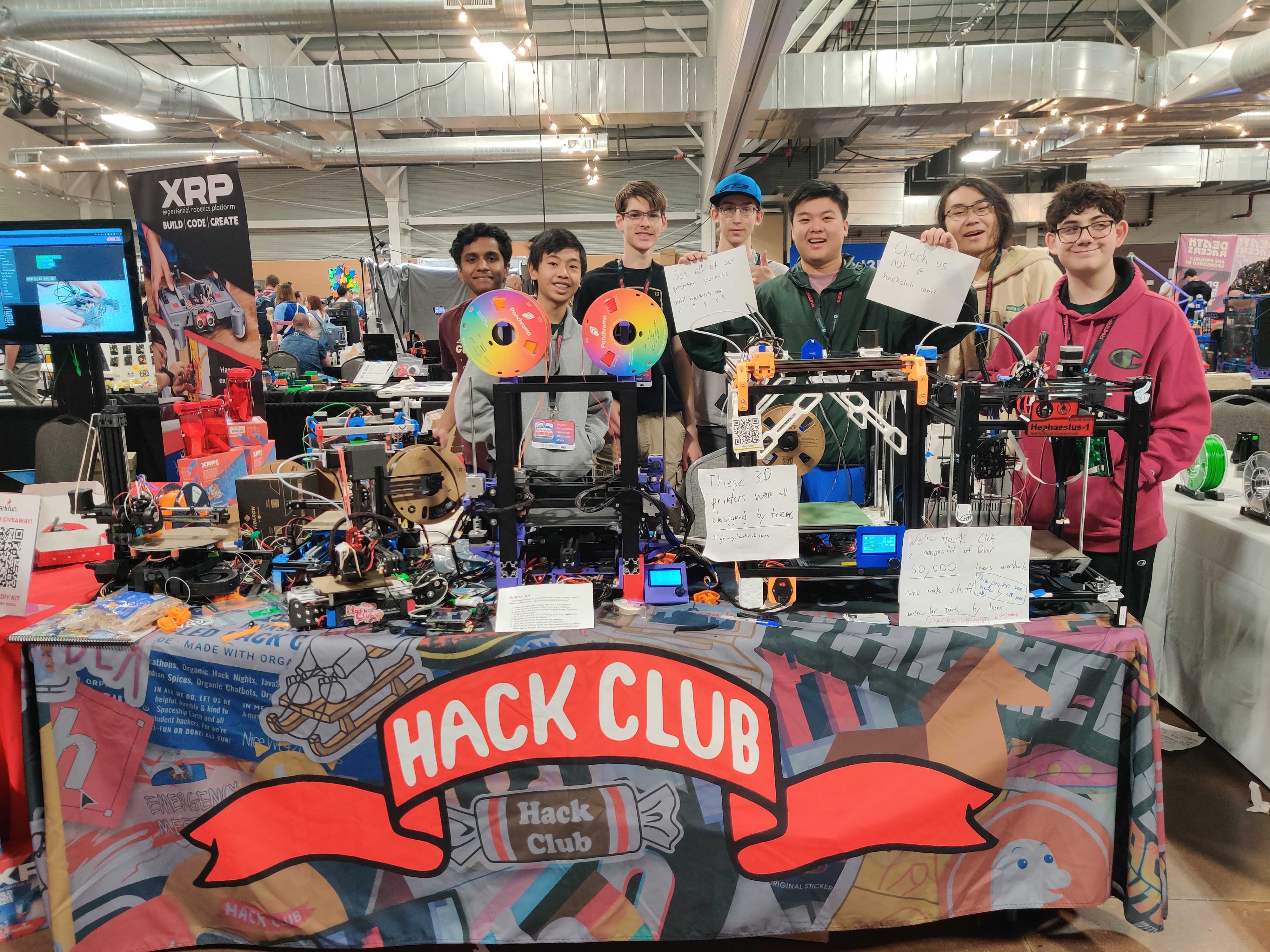
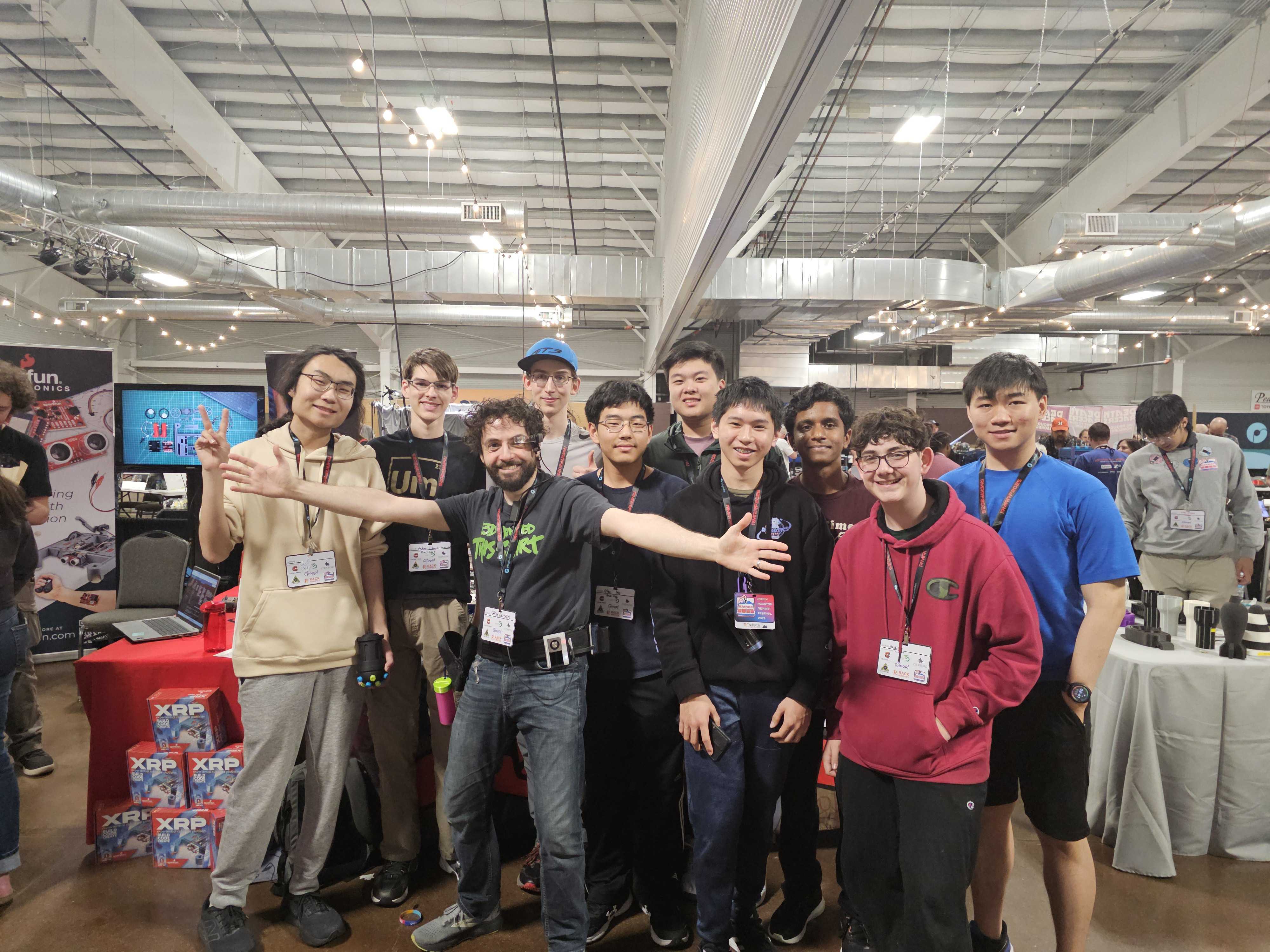
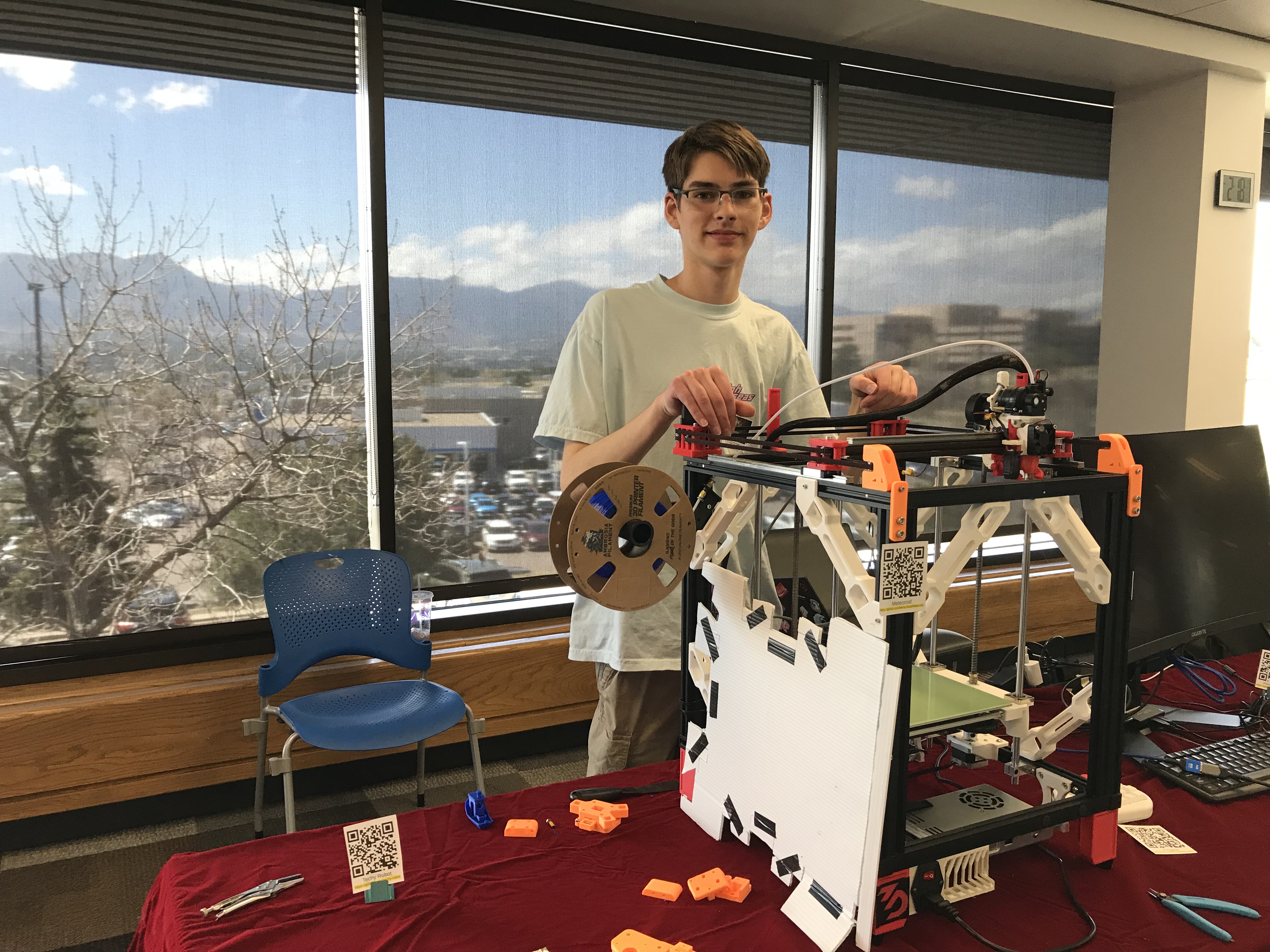
Day 2 my printer was working! I could relax finally, put it at the front of the table, and explore the venue. There were A LOT of interesting booths, and I got some pictures with a few youtubers. I also got inspiration for new toolchanger designs, such as Misschanger, and an unidentified one with round door latch style of lock.
Some group pictures:
RMRRF Day 1 - May 17th, 2025
Most of the day I was working on my printer in the HackClub booth, in the back. I missed quite a few give-a-ways and youtubers stopping by.
In the middle of the day my replacement control board arrived, so I drove back to the airbnb to retrieve it, as well as to get some parts for other hack club members.
I finally got the printer up and running, and I have determined that the sensorless homing is absolutely a driver issue. Swapping out the MKS TMC2209 drivers for BTT TMC2209 drivers with another Hackclubber solved my problems and I could get readings.
I stayed up till 1:30 am getting my printer somewhat opperational back at the house.
Time: 8 hrs.
Driving & setup - May 16th, 2025
Today I packed everything and drove up to the event to meet up with other Hackclub members and get setup.
I didn’t spend much time on the printer itself, only a little bit setting up a wifi hotspot on the RPi.
Time: 30 min
Shorted Motherboard! - May 15th, 2025
I was very foolish today. While configuring klipper and runnign tests I couldn’t get sensorless homing to work and I tried everything. I removed one of the drivers to identify the manufacture of the TMC2209 (it was Makerbase). This might of been my problem, but the system was still on when I plugged it back in. In an instant their was a snap sound, a spark, and smoke appeared from somewhere. The short circuit alarm started going off and the raspberry pi 4 shut off.
I inspected the board and the driver, and there was a blown op amp chip on the signal lines for the socket, and the driver chip had a hool in it as well. Remarkably the RPi was perfectly fine booting separately, so I didn’t dare plug it back in to do a power test with the main board. The main board power test did not go well, no alarms this time but the STM32 chip rapidely heated up too hot to touch, so shut it off.
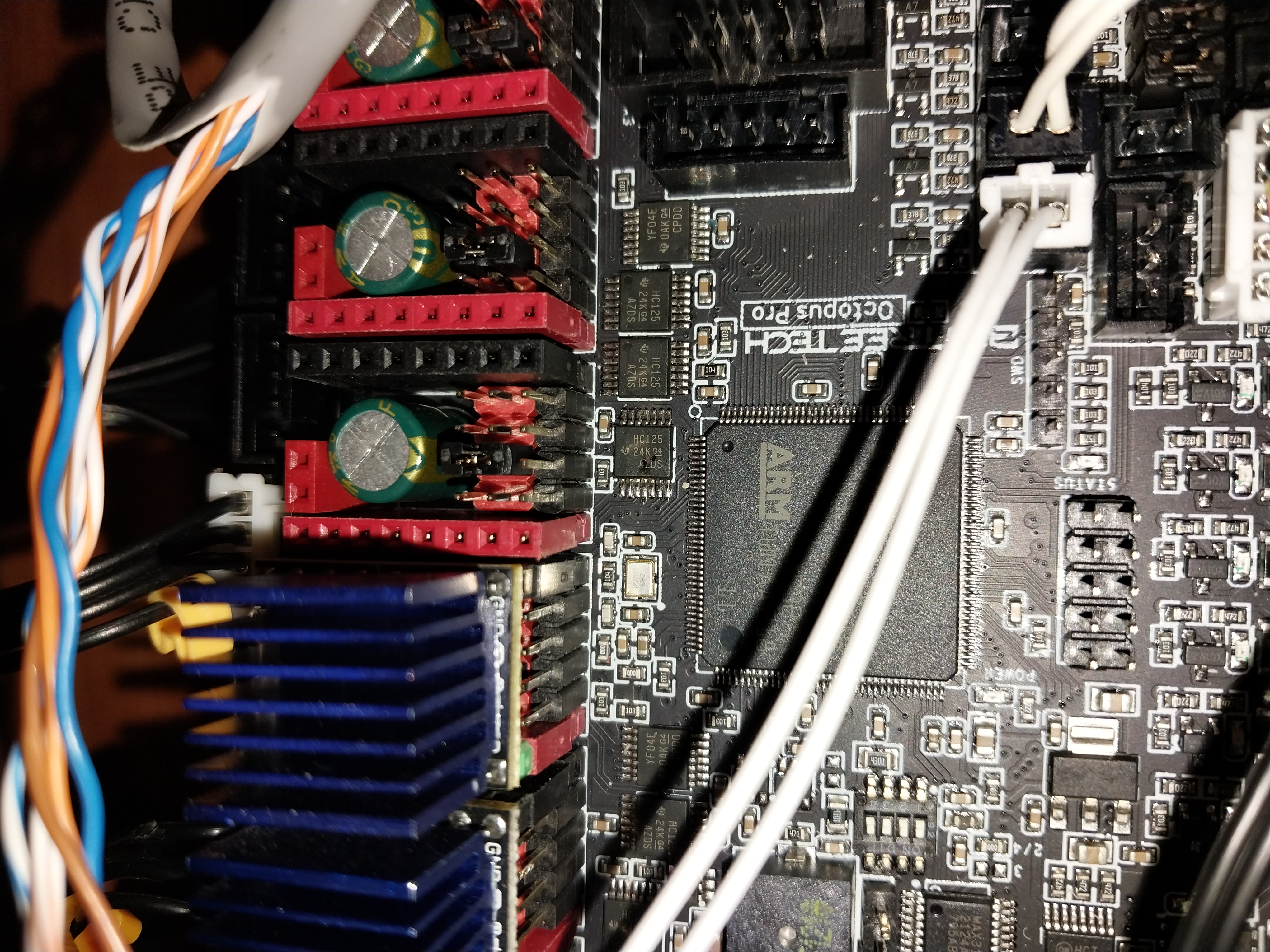
The most likely thing that happend was I plugged in the step stick driver offset by one, connecting the 2 ground pins on the driver to the 5v and the 24v pins on the board.
I rapidely ordered a replacement, because this weekend is RMRRF! It should be delivered on May 17th at the airbnb I’m staying at for the event. I also bought a few extra parts, like screws, copper brushes, a PTC car heater, and air filters. These will be future upgrades, all I definitely need is the control board.
Time: 4 hours
Some Assembly - May 12th, 2025
I finished a lot of the assembly tonight, including replacing some of the toolhead parts again, and adding backing walls.
Time: 2 hours
May 11th, 2025
I discovered an interesting way to attach the chamber mounts: Pull tightly and spin in. I didn’t design the attachment properly but it still ended up working fine.
Time: 30 min
Redesigned toolhead - May 4th, 2025
I spent the past 2 days and today redesigning my toolhead. It now has a BTT EBB36 mount and much better ducts
Time: 10hrs
All Pikes Peak Makes - April 26th, 2025
Today I attended the All Pikes Peak Makes maker faire at library 21c! It was great, I got to share all my projects including my 3D printer, along with my brother. We advertised Hack Club as well, with a lot of potential signups. I tuned my printer live at the event, and managed to print a bad benchy at 350mm/s. I still need to completely replace the parts and add the toolchanging head.
Time: 7 hrs
Prep for event tommorow - April 25th, 2025
I spent awhile building sub-assemblies and trying to make my printer functional for tomorrow. I ended up not finishing the entire new assembly, and since my new printer is similar enough to my old printer, I decided to replace some compatible parts and leave the rest. I managed to cut myself multiple times extracting the bearing towers from the old parts.
All I ended up doing: Set up the RPi4 completely with klipper, attach it, and replace the front towers.
Time: 5 hrs
Printed all the parts - April 24th, 2025
All my parts are printed, there was a lot of trial and error initially printing the orange ASA, I had to make sure my chamber was sealed and all fans were off.
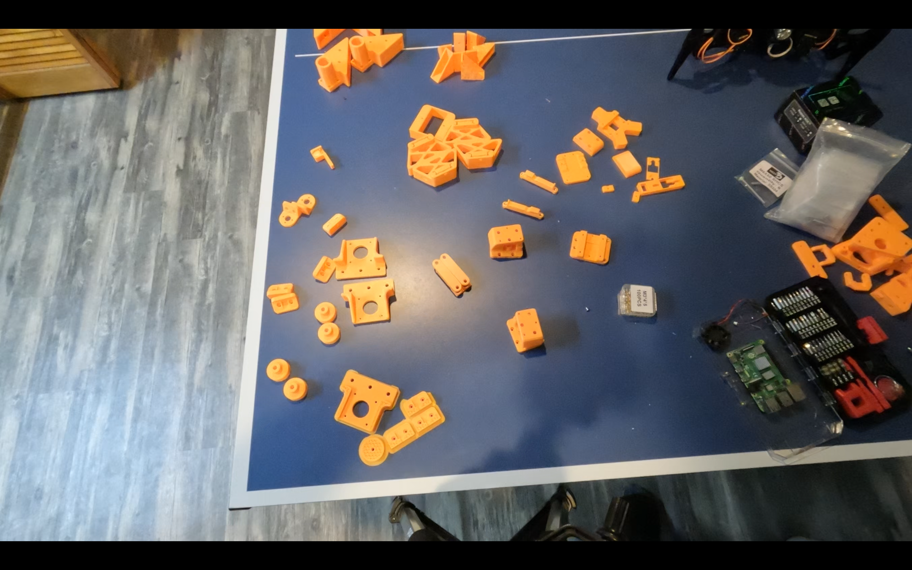
Time: 3 hrs
Parts Arrived! - April 19th, 2025
All my important parts arrived! Some parts are going to be reused from old projects as well, which aren’t shown here
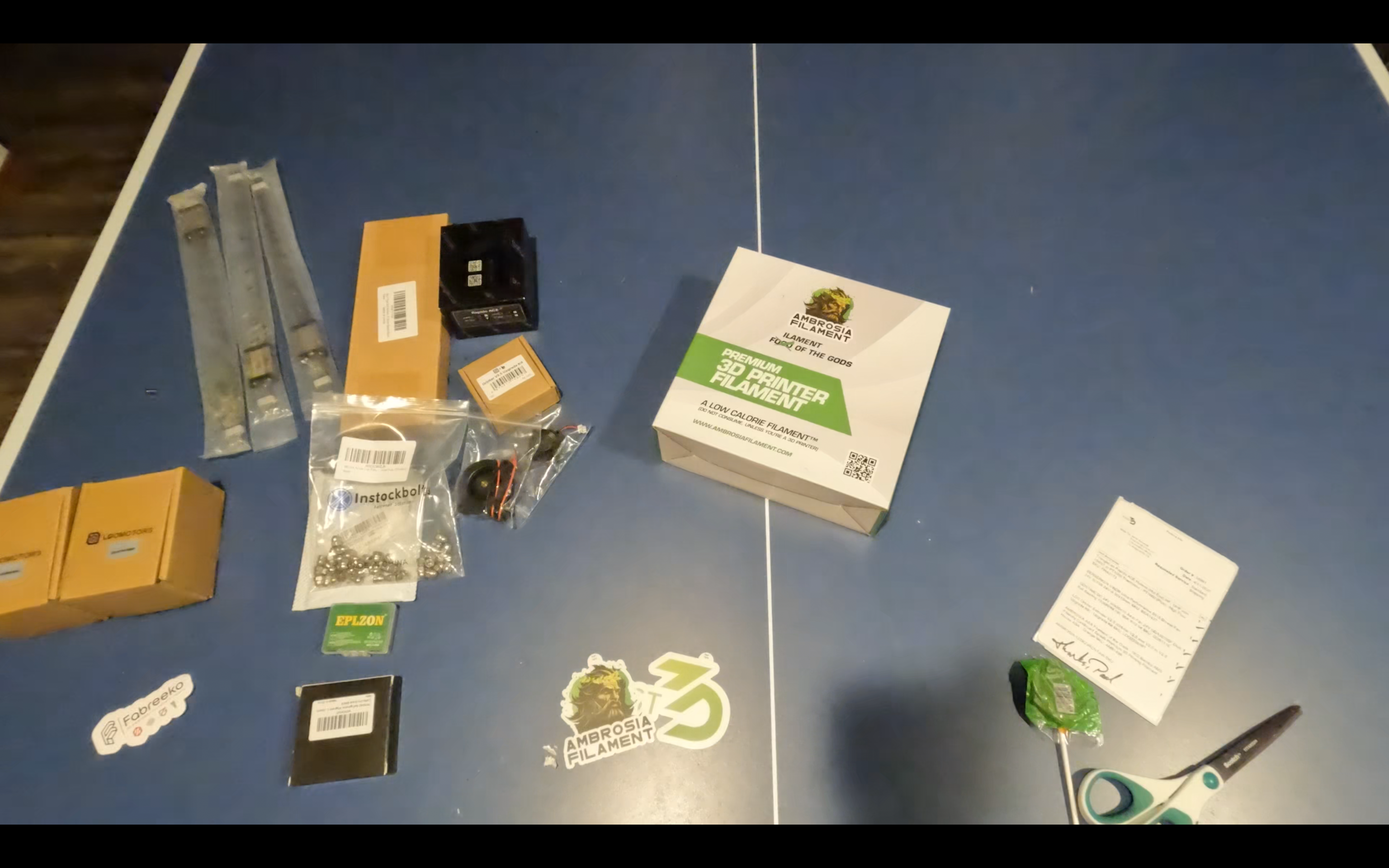
Time: 30 mins
Ordering Parts! - April 11th, 2025
Today I ordered a majority of my parts! It took a lot longer than expected, and I still haven’t orderd my complete BOM. I only ordered “the big items,” like hotend, motors and extruder.
Time:2 hrs
April 6th, 2025
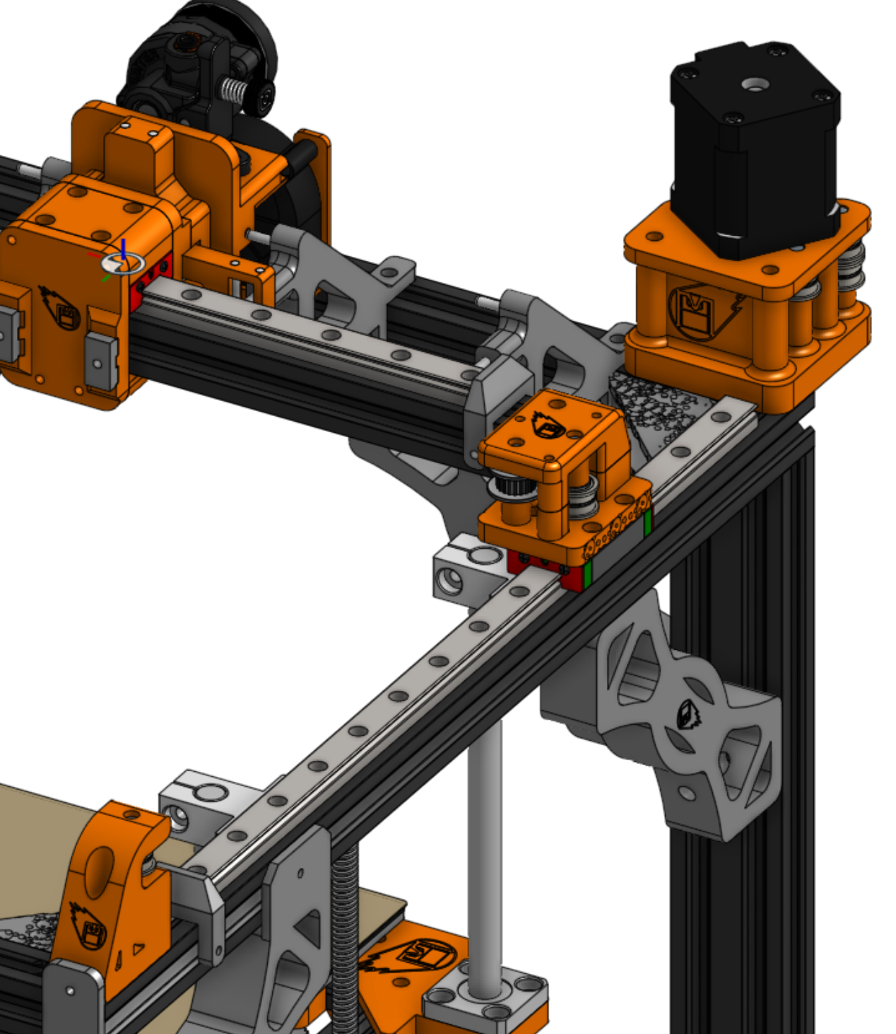
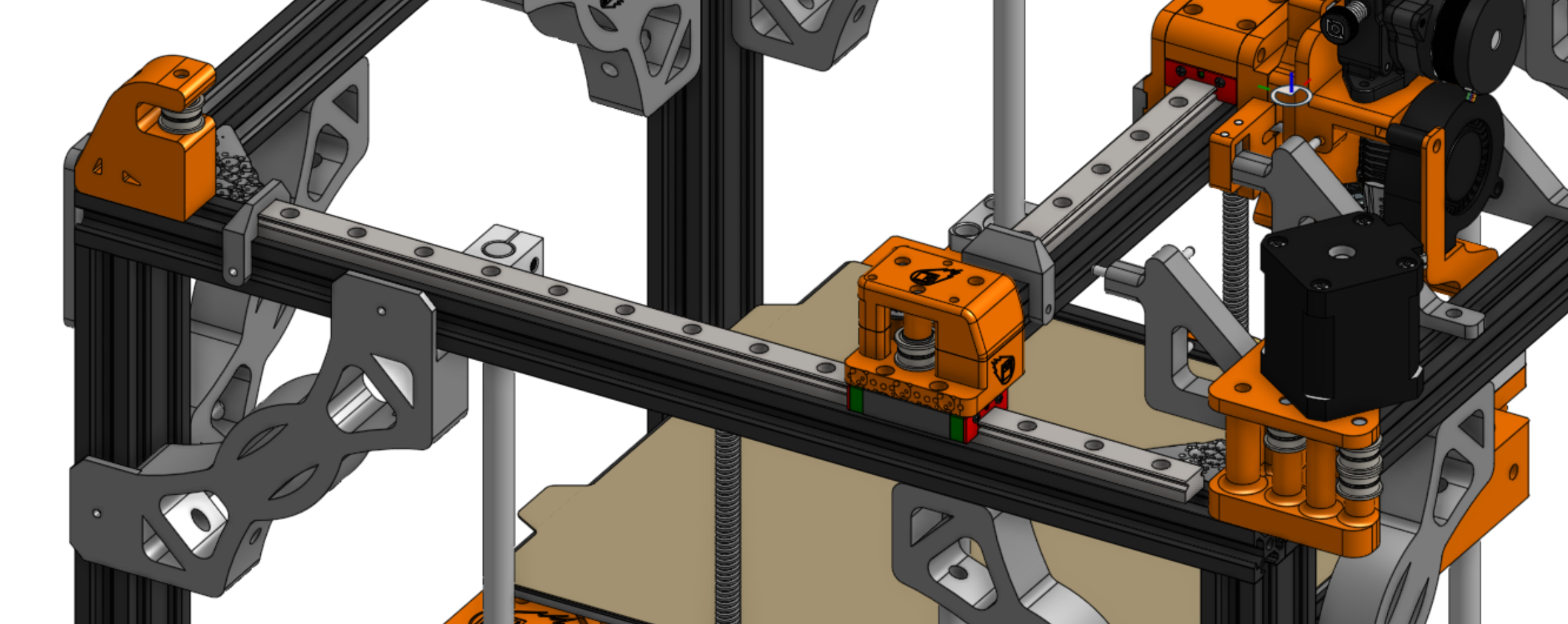
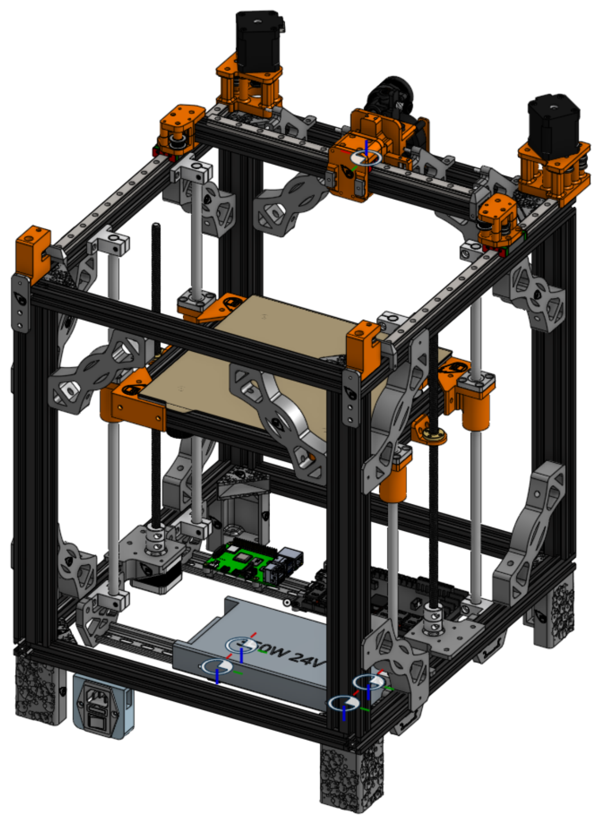
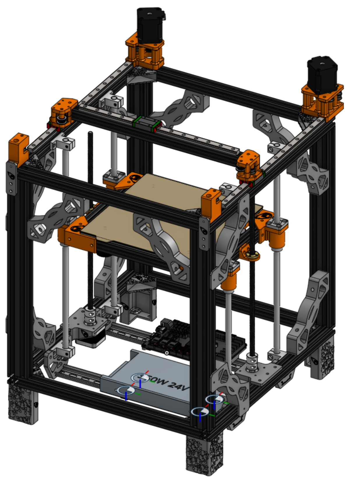
After some conversations with other members of the 3D printer community, some felt that the XY motion system design is too close to the original ZeroG mercury printer design. I have decided to make some modifications to the look without impacting functionality.
New XY gantry pictures:
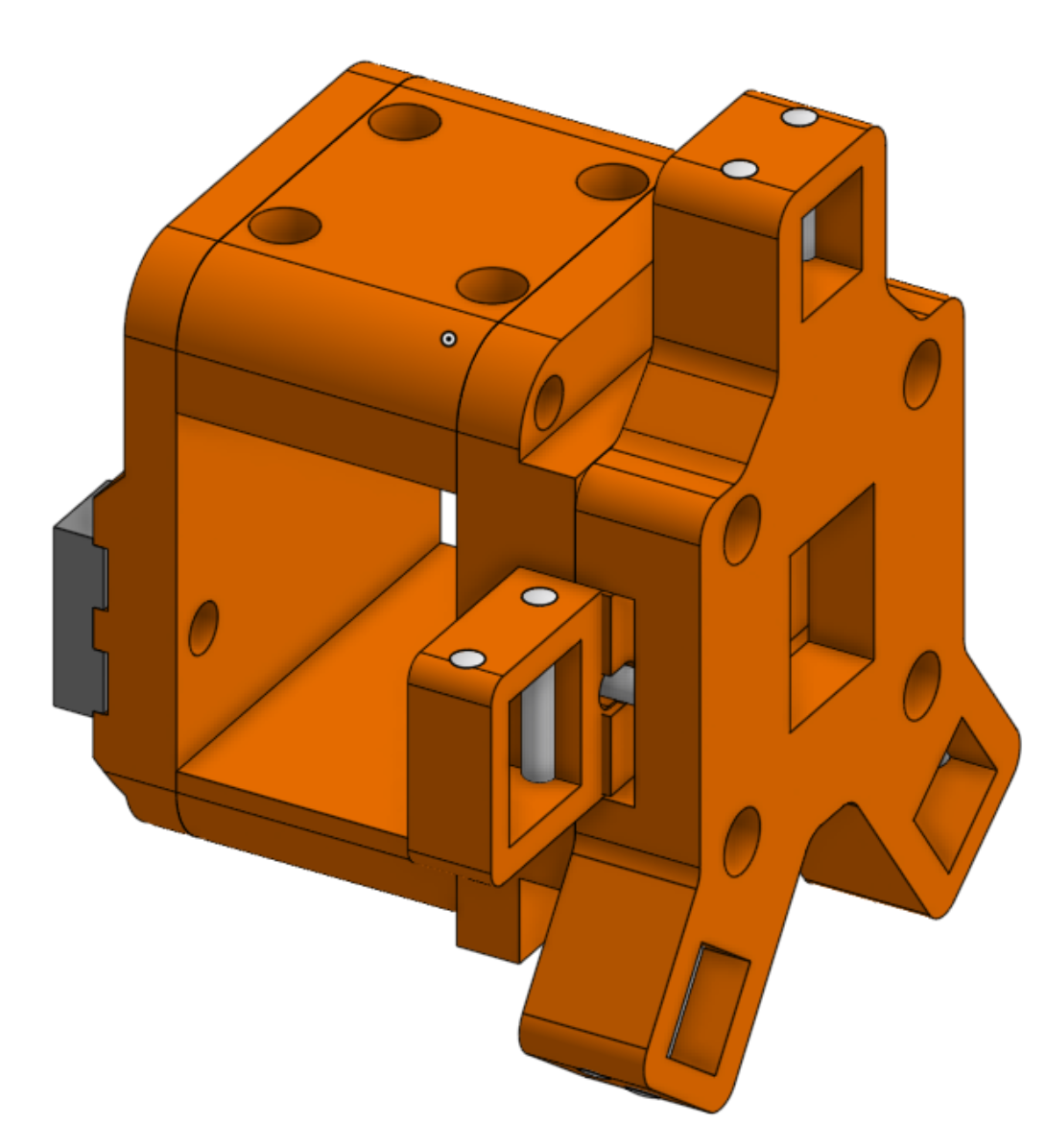
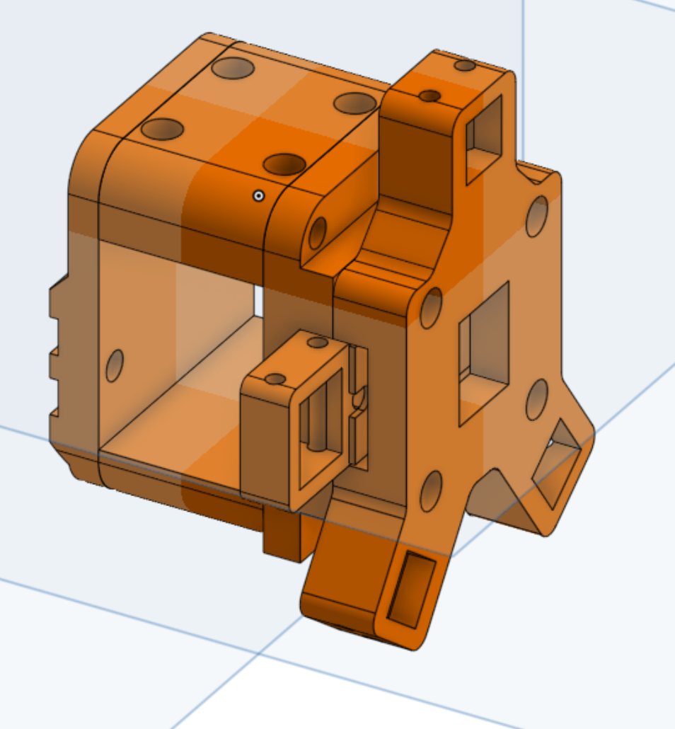
I also want to show some clarity on how my toolchanger design is different and improves on Daksh V2
Pictures to start:
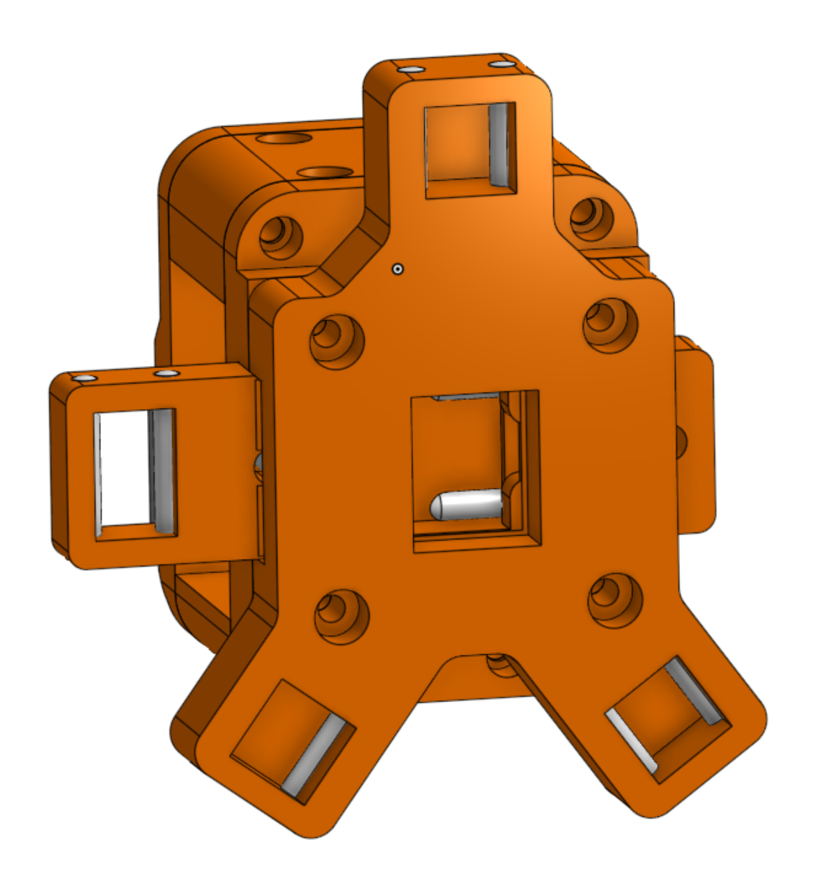
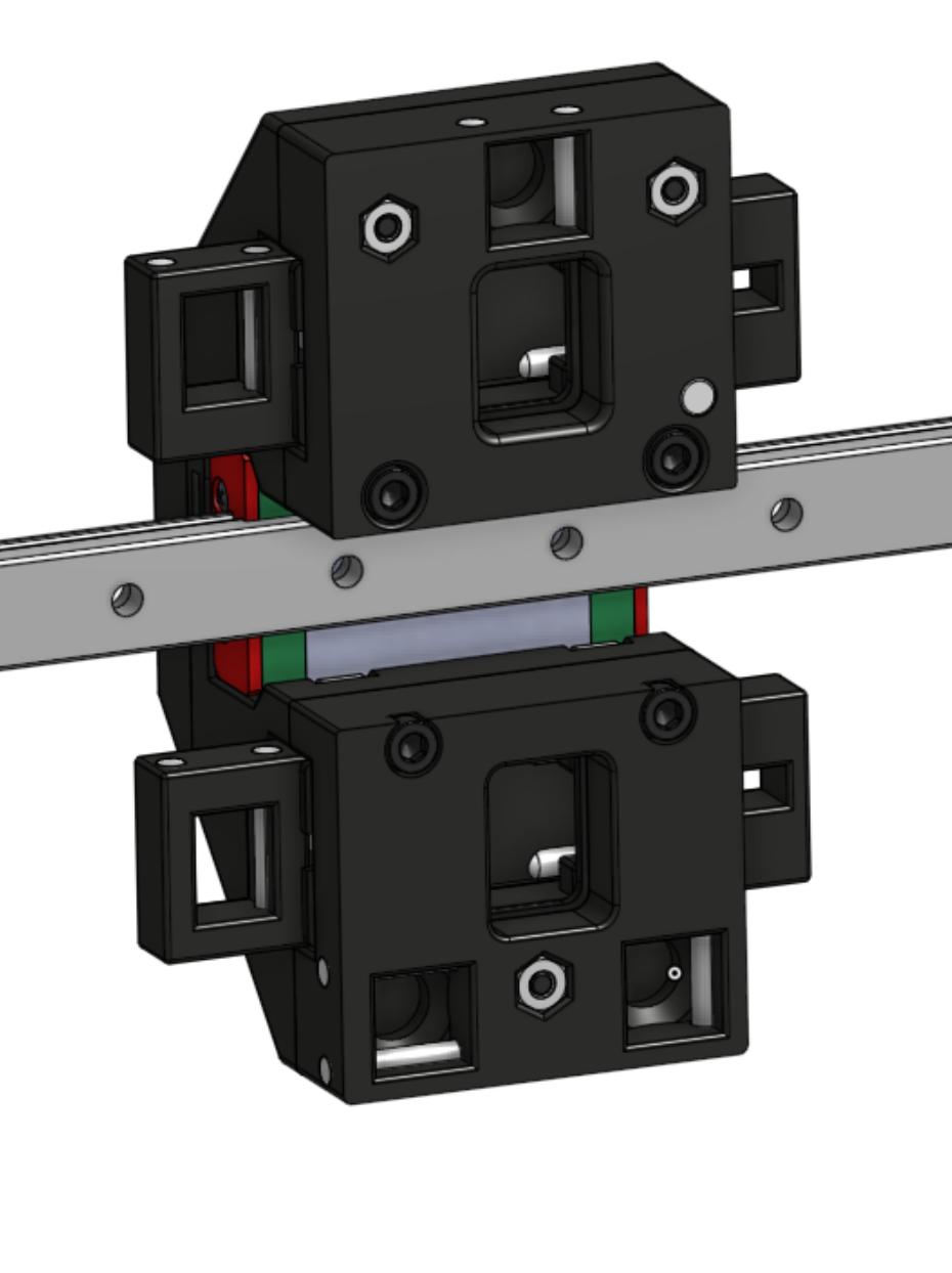
My design is a single lock system that is centralized, all the force applied by thelock is put in the direct center of the kinematic mount, distributing the force evenly. Daksh V2 has two separate locks, one on the top and one on the bottom, applying an equal amount of spring force on unequal mounting.
I also noticed in the Daksh v2 toolhead that two of the three mounting points have the rods facing vertically, and the 3rd horizontally. I am concerned that this adds a small amount of uneven rotation to the system. If you look up normal kinematic mounts, the V-grooves are pointed in towards the center, and restrict all degress of freedom. Having each mount point facing a different direction likely applies uneven force. I wanted to fix that.
Time: 4 hrs
Released first version 0.5 (for Hackclub Infill at least) - April 5th, 2025
I made a lot of small design tweaks to get things to fit on the tool change, or other.
I designed a RPI mount, and endstops and docking places as well.
I also switched to an inset 3010 fan for the hotend to reduce horizontal space taken, which should save 10mm. I really want to fit 4 tools in!
I have exported all the sub-assemblies that I think are important and put them into the same folder structure as found on onshape. I left out some small part assemblies that are found in later big assemblies to save space.
To print actual parts, see the STLs folder, though you could always pick out individual parts from the STEP assemblies.
This is release V0.5, as I have not tuned any of the parts to work with ASA, or revised my design with things that didn’t work. Onshape Link
BOM is also finished.
I designed a little adapter board I called Klipper to CACKLE. It basically takes USB-c input and 24v power, and converts this to my CACKLE layout spec and RS485 communication protocal. It uses a CH32 chip to process the commands and output equivalent Luos spec datapackets over the bus to my system.
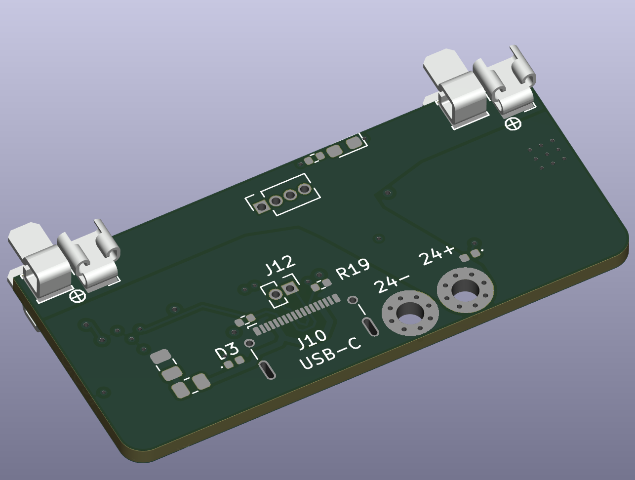
Final picture
Time: 6 hrs
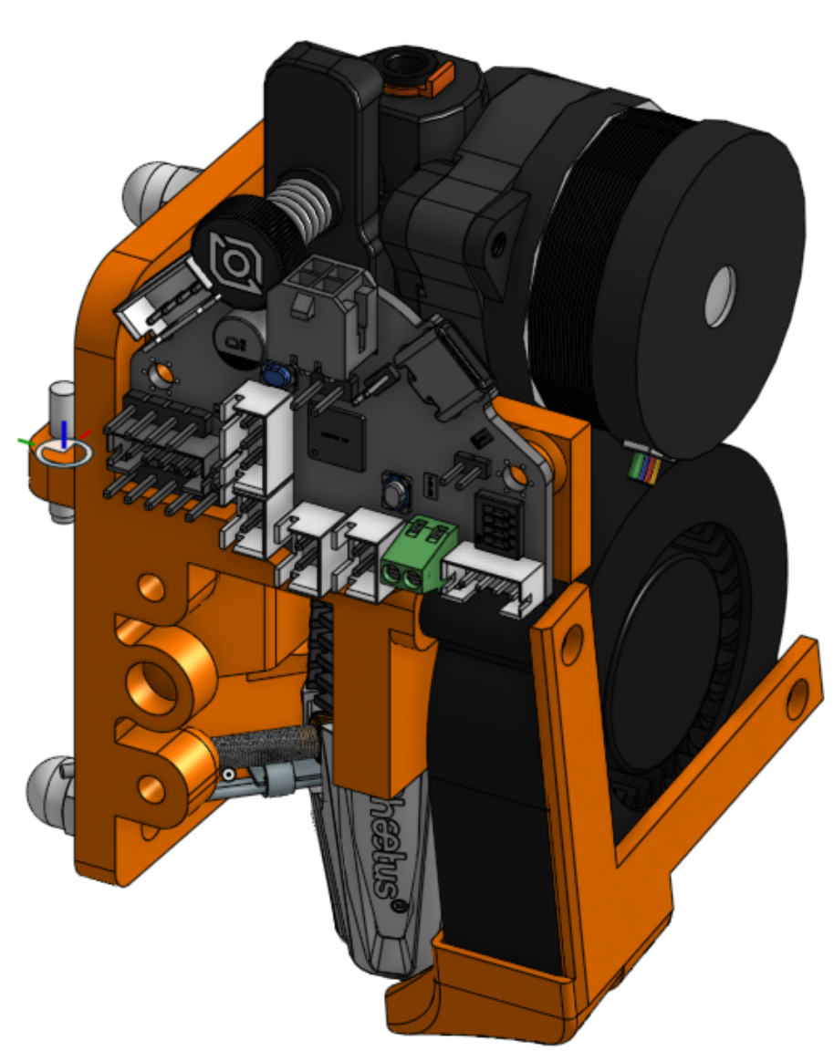
Finished first toolhead - April 2, 2025
Finished my first toolhead!
Fan air path cutaway
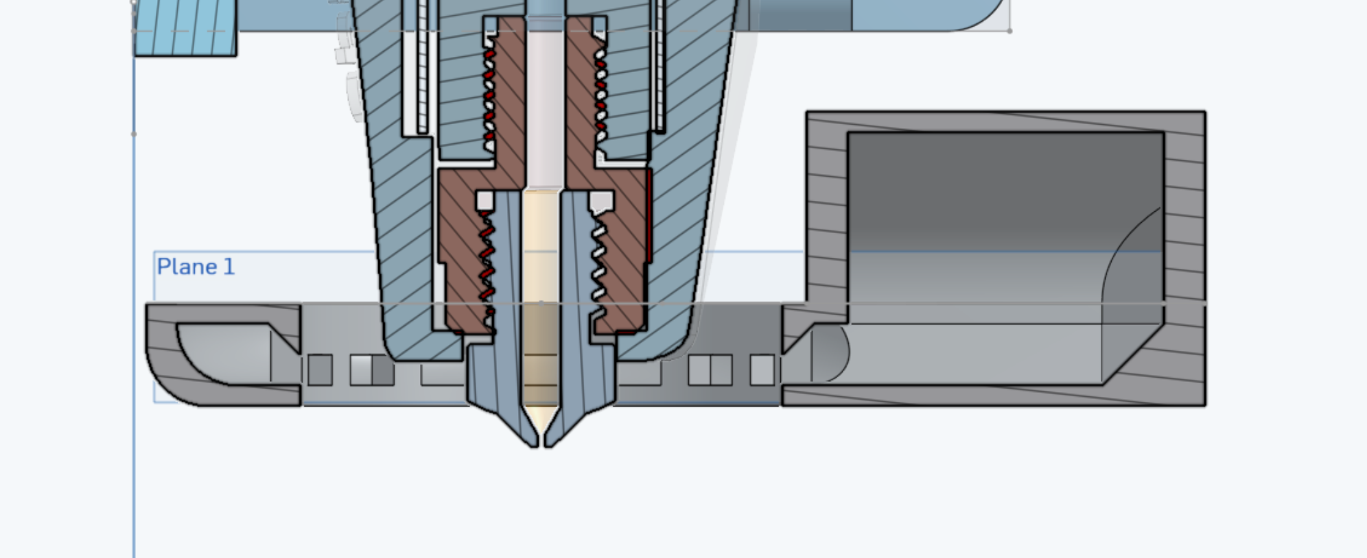
Finished toolhead, with a Phaetus Rapido 2.0 UHF, Orbiter 2.5, a 5015 blower, and a 4010 hotend fan.
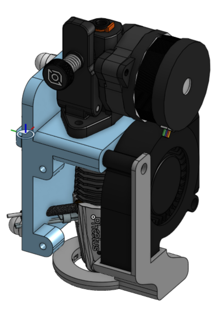
Time: 2 hrs
Finished Assembly of Toolhead carriage - March 31, 2025
Time: 1hrs
Finished Toolhead carriage and lock - March 29, 2025
Now I need an actual toolhead, a PCB design and the BOM. So close to completion!
Time: 3 hrs
Finished top motion system - March 28th, 2025
I finished designing all the motion system parts today. Only the toolhead and extra little parts left now! The toolhead is going to be complex still, and I may need to change my gantry back to the rail being mounted in front instead of on top. The Prusa XL has front mount rail, and so does Daksh V2.
I realized that my frame was the wrong shape! It was supposed to be 410 by 440, not 410x410 ! I also spent about an hour fixing other random dimension errors or things I missed.
I added my updated logo design to several parts as well. I only put logos on parts that are personalized or parts that I can reasonably claim my own. Several of the motion parts are based on other’s works and I can’t plaster my logo on it and erase credit if all I did was change 3 distances.
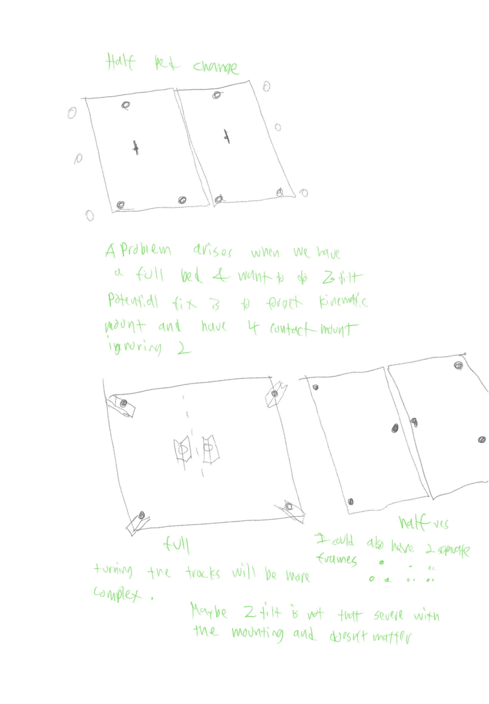
I also had ideas for bed changing mechanisms
Time 8 hrs
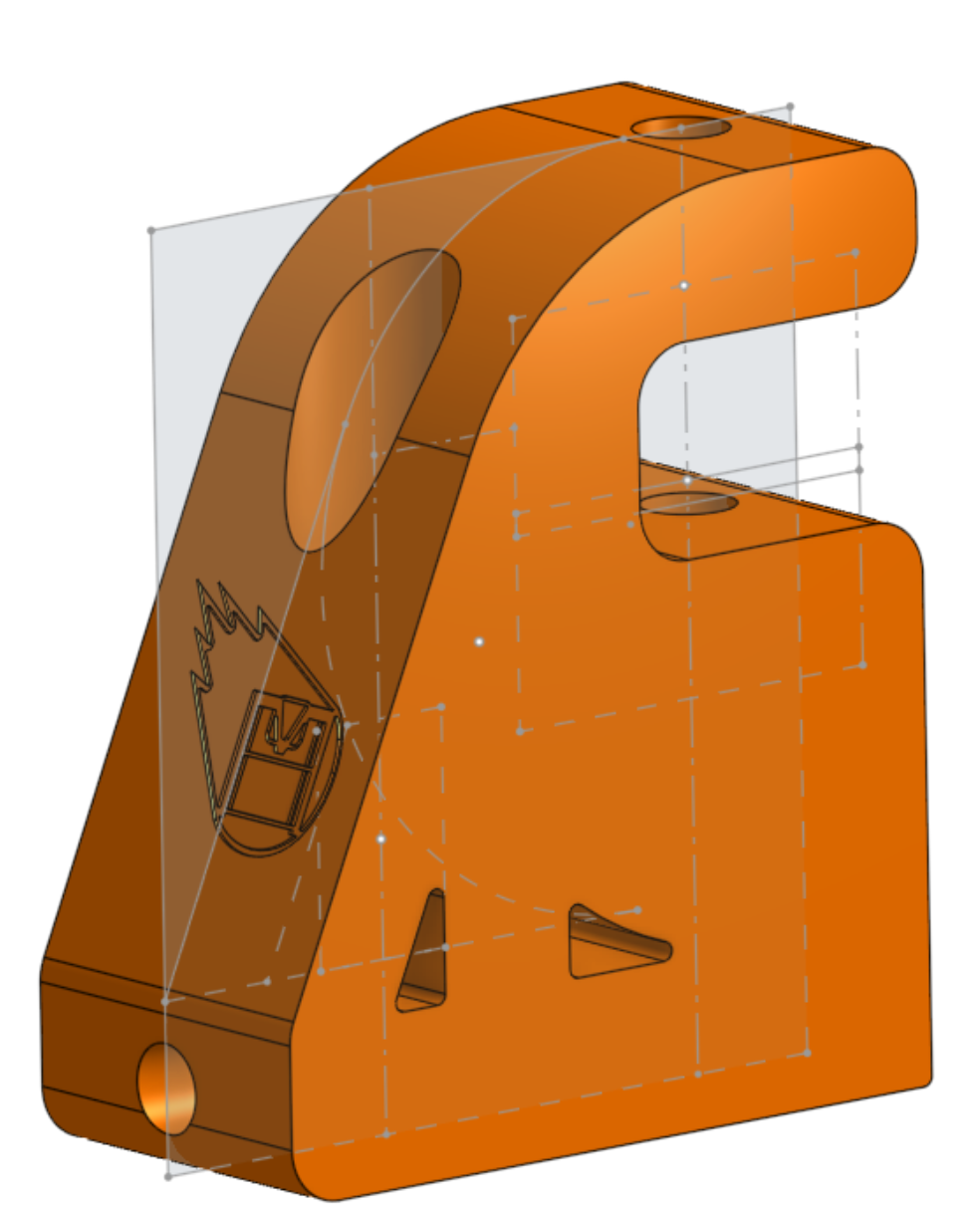
Finished X axis - March 27th, 2025
X axis is finished! (doesn’t include toolhead)
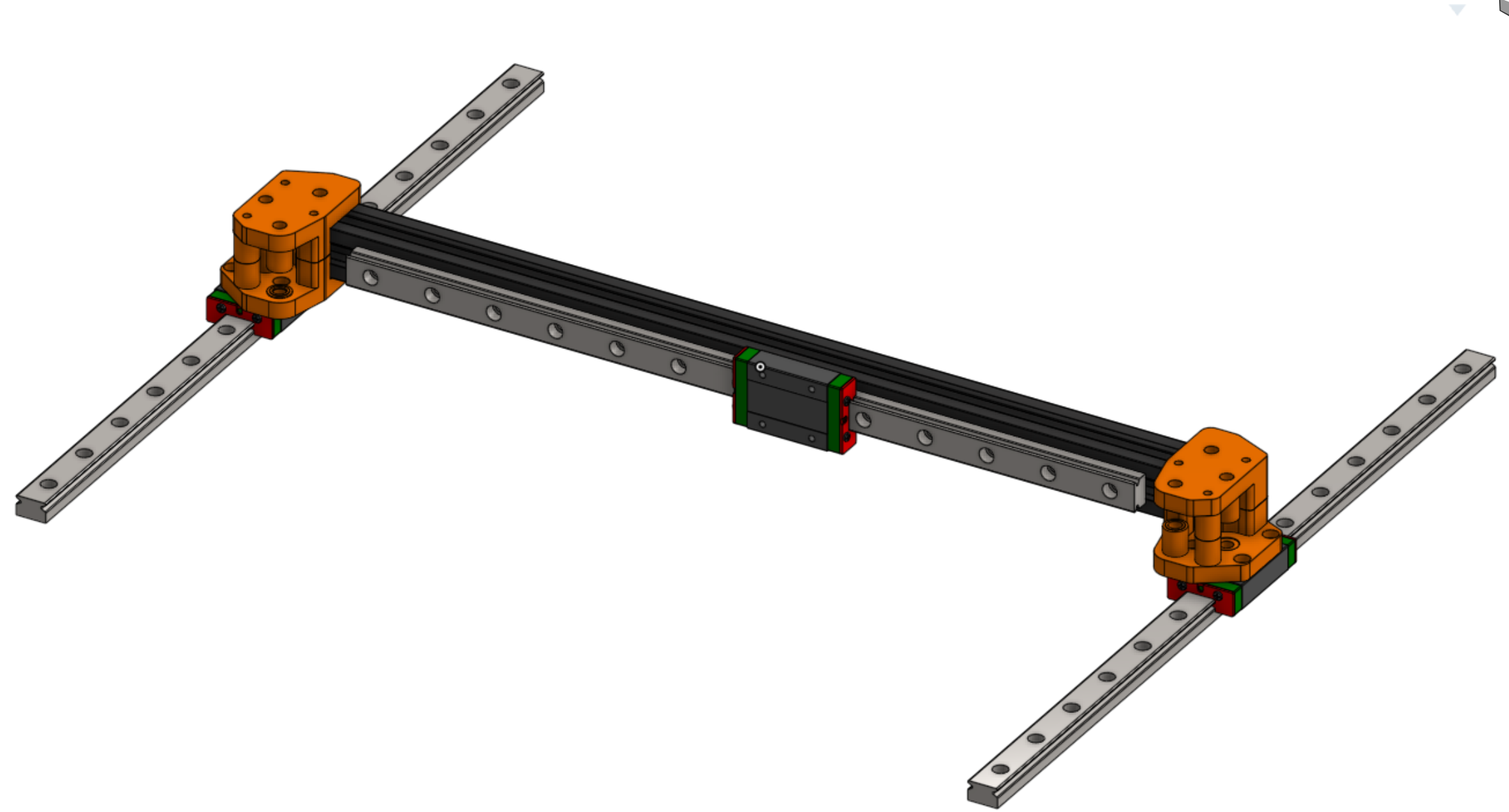
I also changed the pockmark size on the base standoffs, to make the design bigger.
I added all my base and accent colors to this now, spicing it up. Stationary parts are Grey, moving parts are Orange.
Time: 4 hrs
Started on X beam March 25th, 2025
Didn’t take any pictures, but I am mostly finished with the x joints
Time: 2hrs
Add Electronics base - March 24th, 2025
I changed the bite marks on the corner peices to an actual meteor texture that I made. I will put that texture on all non-critical parts now to spice things up!
I also spent some time designing the bottom electronics enclosure parts.
I also spent 2 hours researching using USB for all peripherial devices instead of CANbus, and it seems like it has a lot more potential without much downside. CAN bus is better for redundancy and long distance, which is not really used for 3D printers. It also ends up being a drag for toolchangers with hotswap, and for high throughput data required by cameras. I just need to use USB over a sheilded cable, and have a hub! The LDO Nitehawk SB boards look pretty cool, with that special molex connector with big power lines and small datalines. I could design a hub for that connector! Similar to birds nest but cheaper and with USB-c.
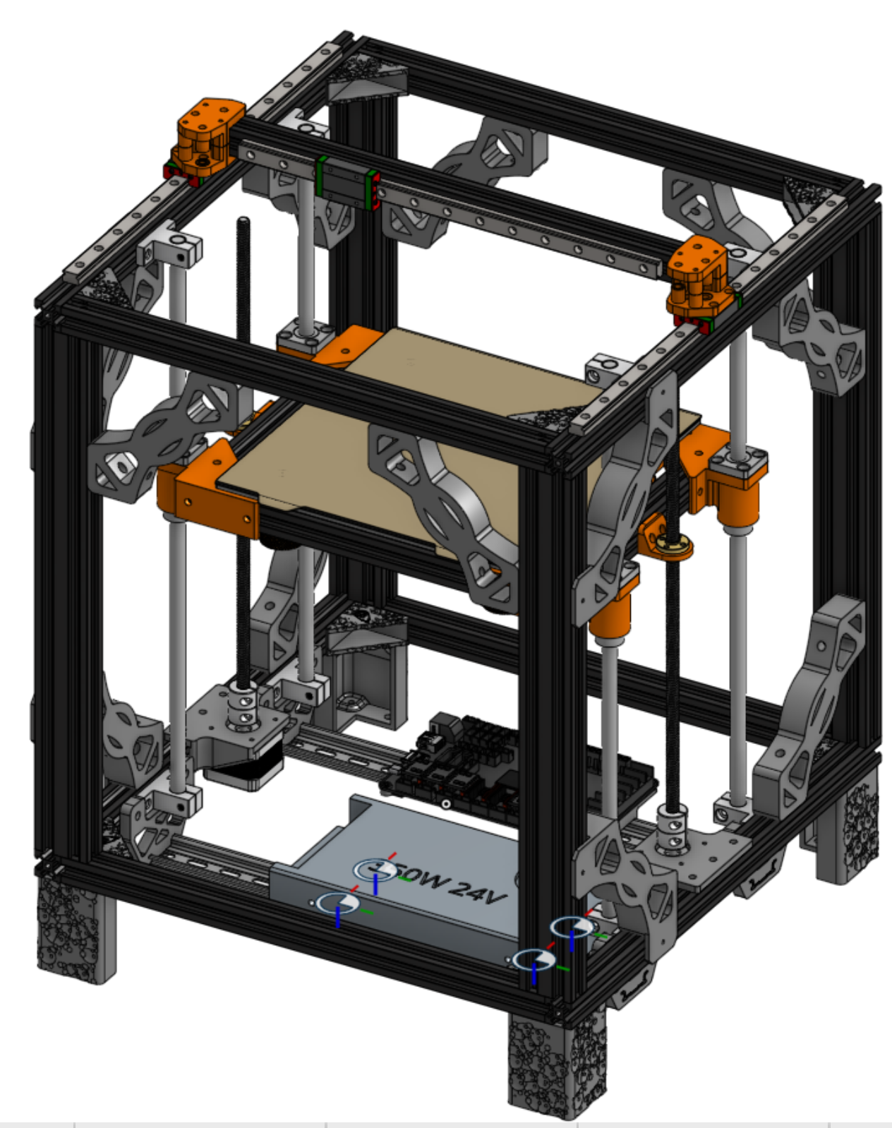
My printer is really shaping up! I have all of the base designed and assembled. I now only need the top motion, toolchanging toolhead, and possible enclosure! I’ve reached the point where I now consider it prudent to include a main step file in the repo, with half the mechanical design finished.
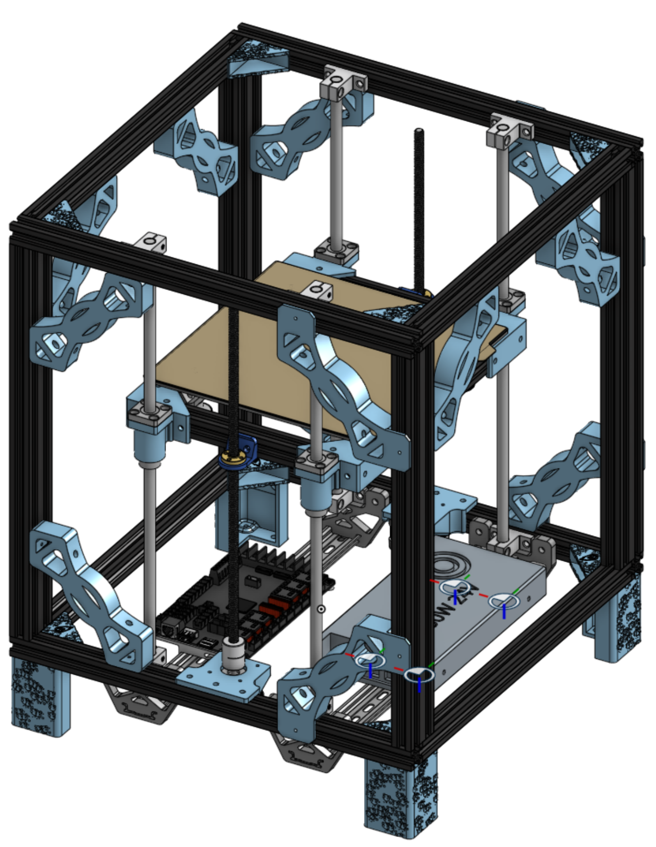
Time: 8 hrs
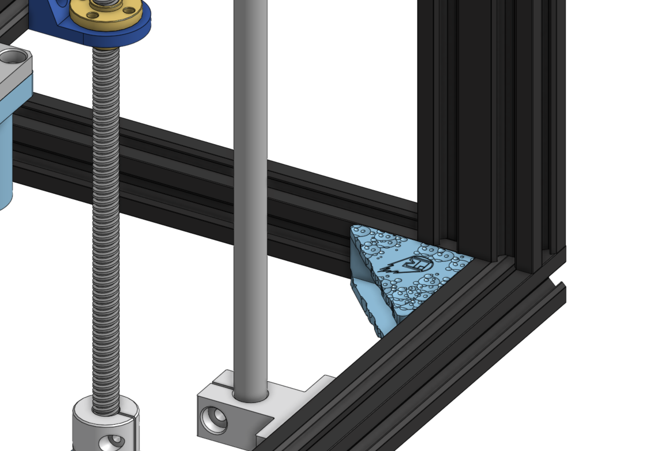
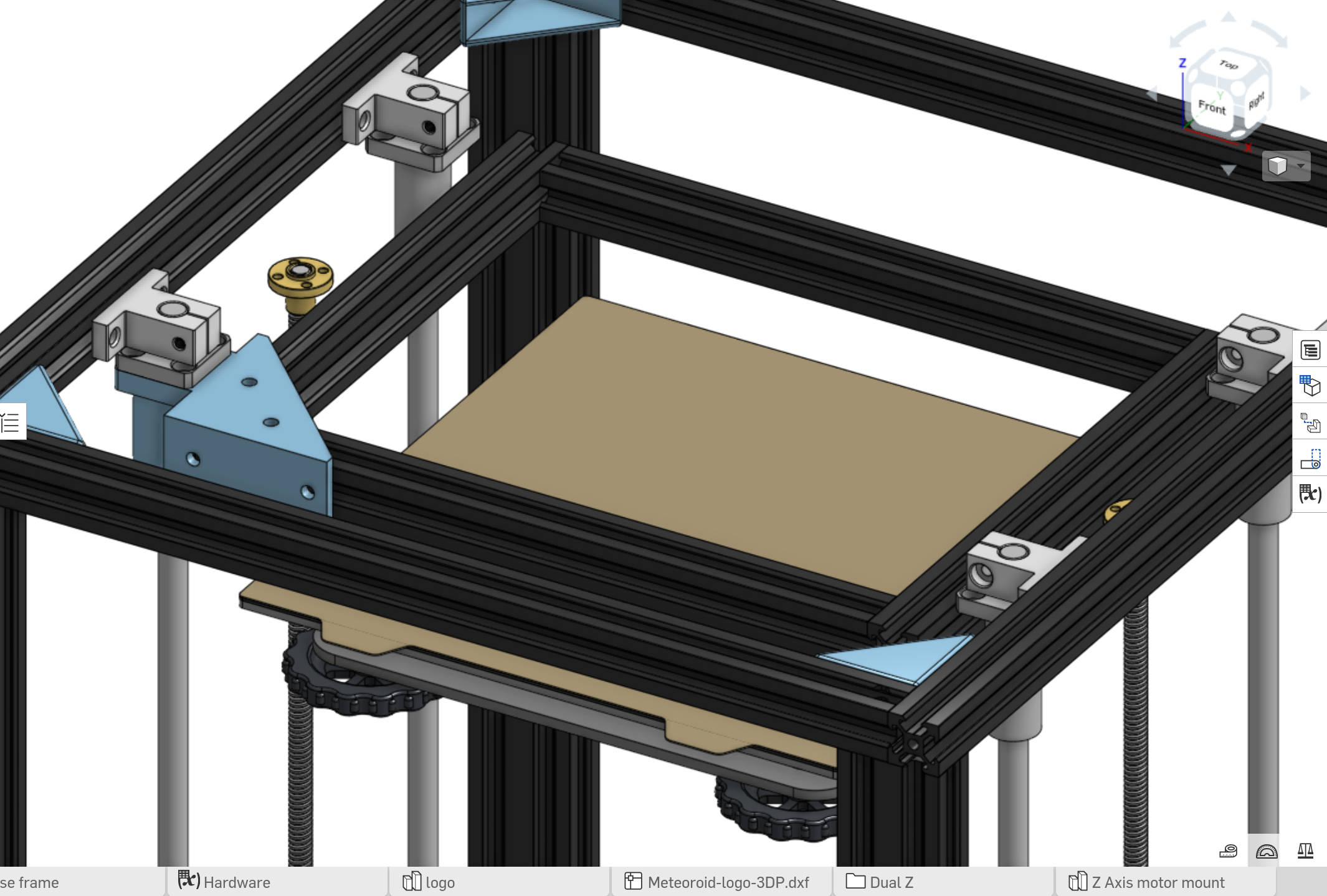
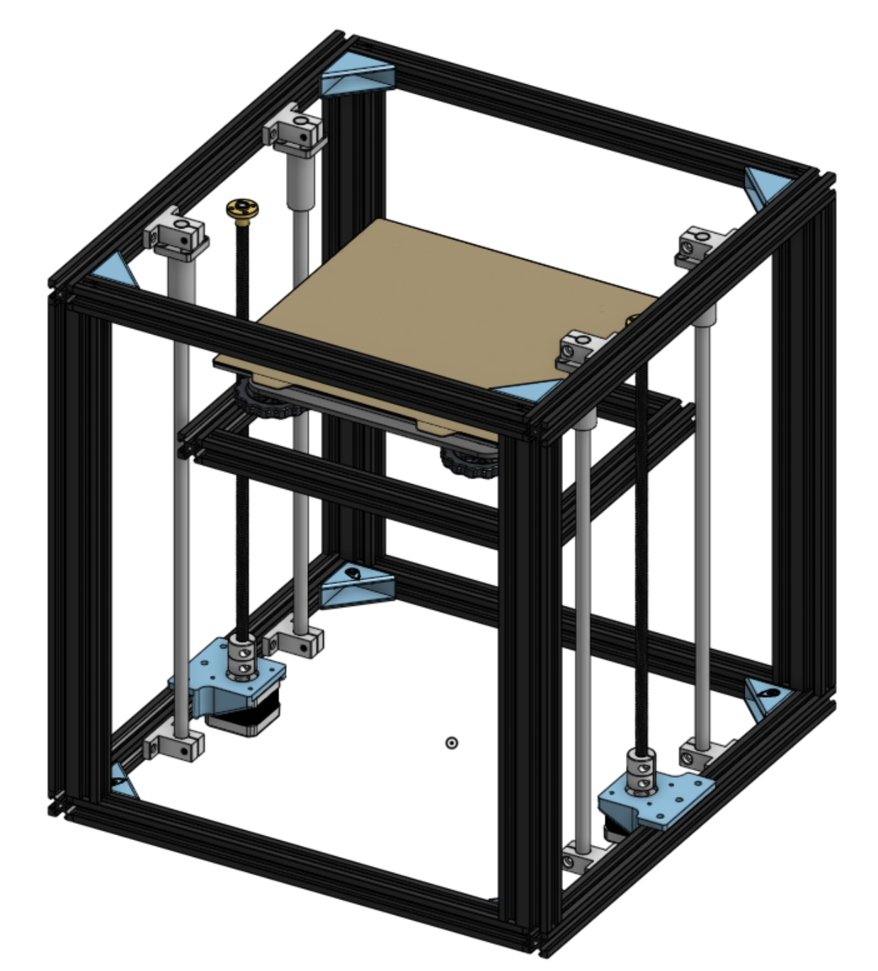
Finished bed frame - March 23rd, 2025
I have attached all the parts and knobs and stuff, and added some motion capability.
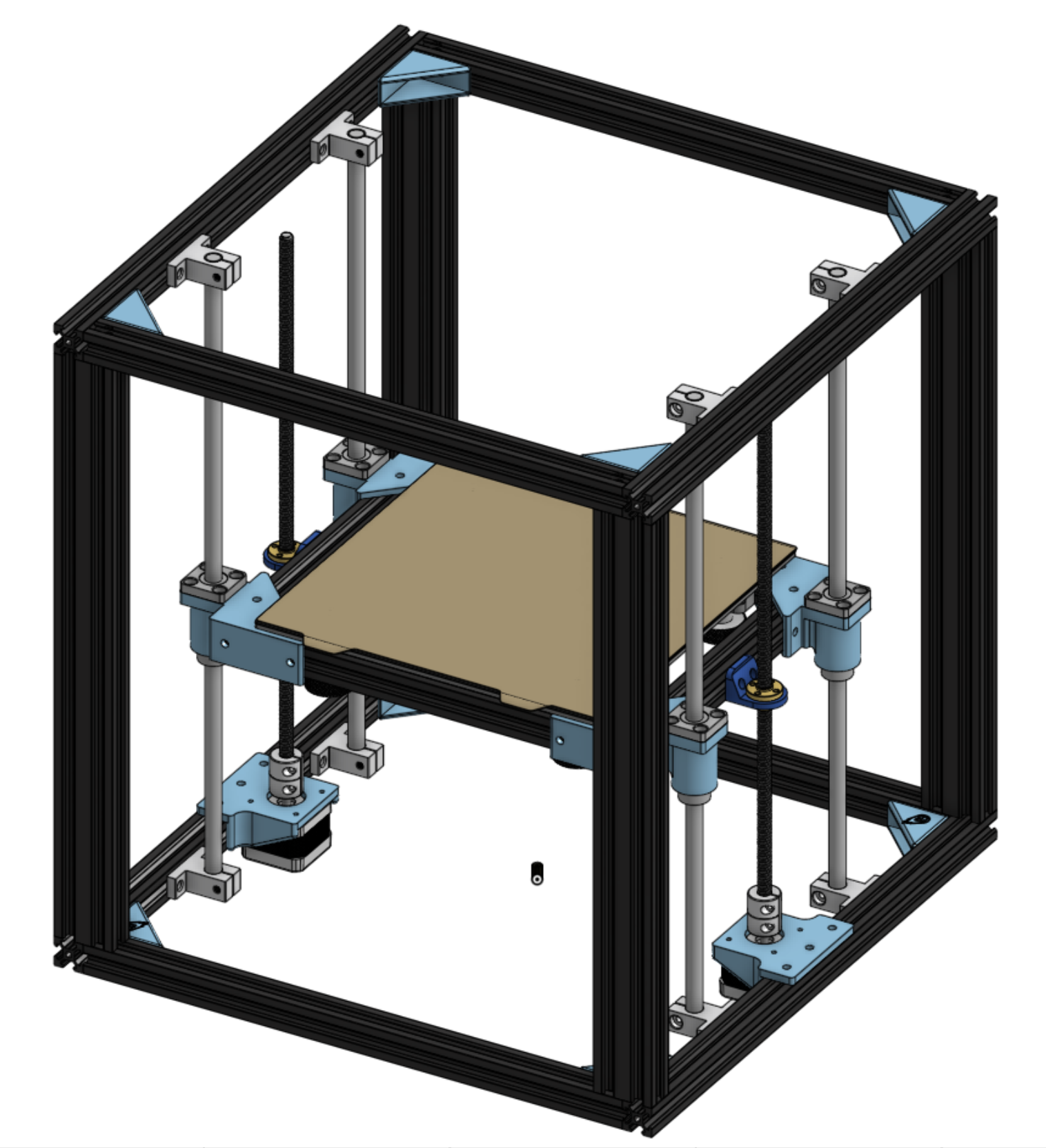
I also add fun bite marks to some the pieces, in imitation of a meteor.
Time: 2hrs
Updated Icon - March 22nd, 2025
I changed the design a bit to emphasize the M dip and make it look somewhat more like a toolhead.
![]()
Time: 1hr
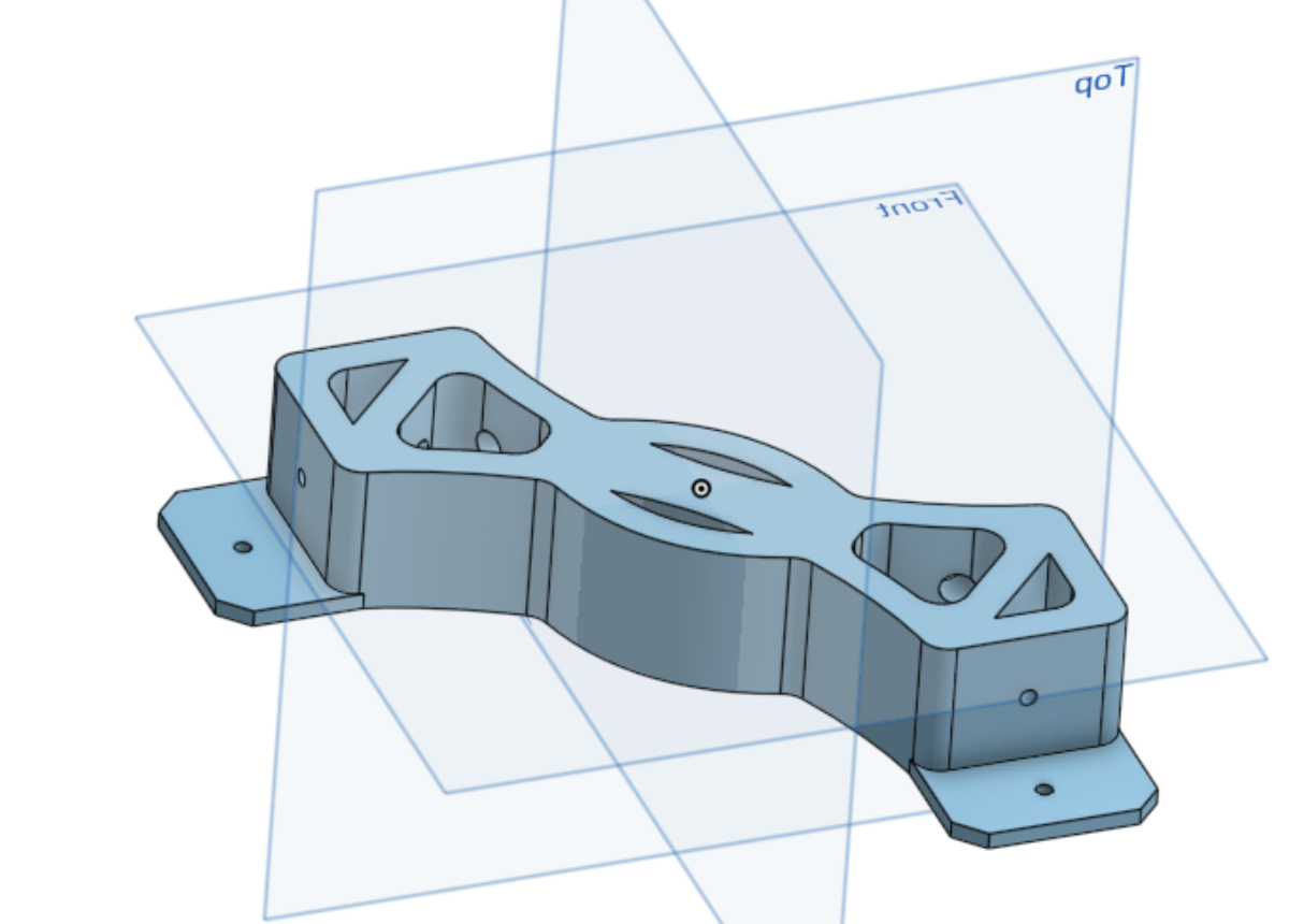
Started bed frame design - March 18th, 2025
I created a combined bed corner and z linear rail peice. I hope it is rigid enough!
Time: 1hr
Added Z axis rails - March 17th, 2025
Time: 1hr
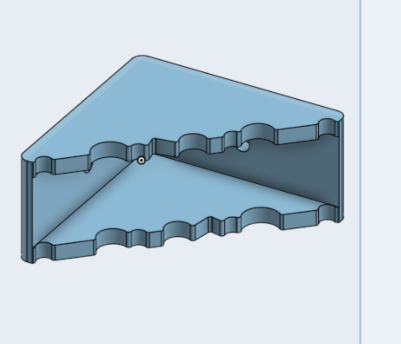
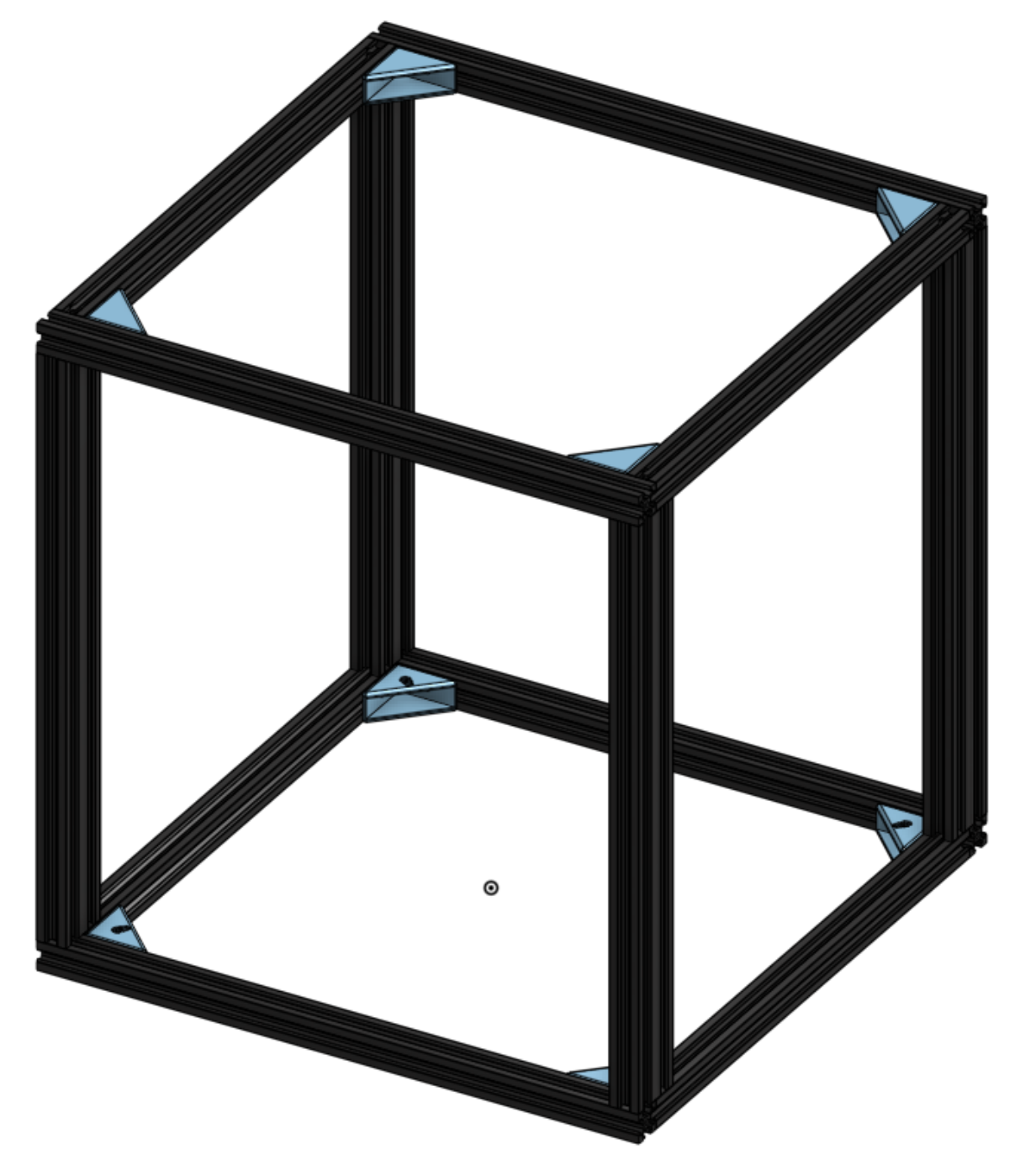
Started frame stiffener - March 9th, 2025
I designed a fun frame stiffener peice
Time: 2 hr
Finished Logo digital design - March 8th, 2025
I spent quite a few hours working on turning my drawings into a logo for my printer. I created multiple versions of it for different situations and for 3D.
Final logo:
![]()
My Process for creating Logo types
- Create the base color logo. Use offset live path effect with rounded corners and then flatten it to a normal object for the internal light colors. More control than the Path Outset tool. Break it apart and delete the weird extra small shapes. Make sure to name all objects, and have a layer for the printer and layer for the burn
- Copy and start on two-tone version. Delete the 3rd inset color. Make sure the color pallet only has Primary and Background colors. Change all lines to Primary color, and make sure everything else is a fill color. Re-create the burn internal offset except without internal edges. The burn has to go behind the printer now.
- Copy and start on black and white version. Only change necessary, which should just be the colors
- For Mono, take the path difference of the trail and the the background so that you have no background fill object. Delete the fill object for the printer. Now it should be transparent and have only one color
- Finally, to get a logo that can be extruded in 3D, convert all strokes to paths, boolean union on all paths, Get ride of all groups and layers, and save as a DXF R14 file without changing any of the defaults.
Time: 6 hrs
Base Frame - March 5th, 2025
Finished base Frame today, I just need to add stiffeners
Time: 30 min
Logo ideas - March 1st, 2025
Some logo ideas
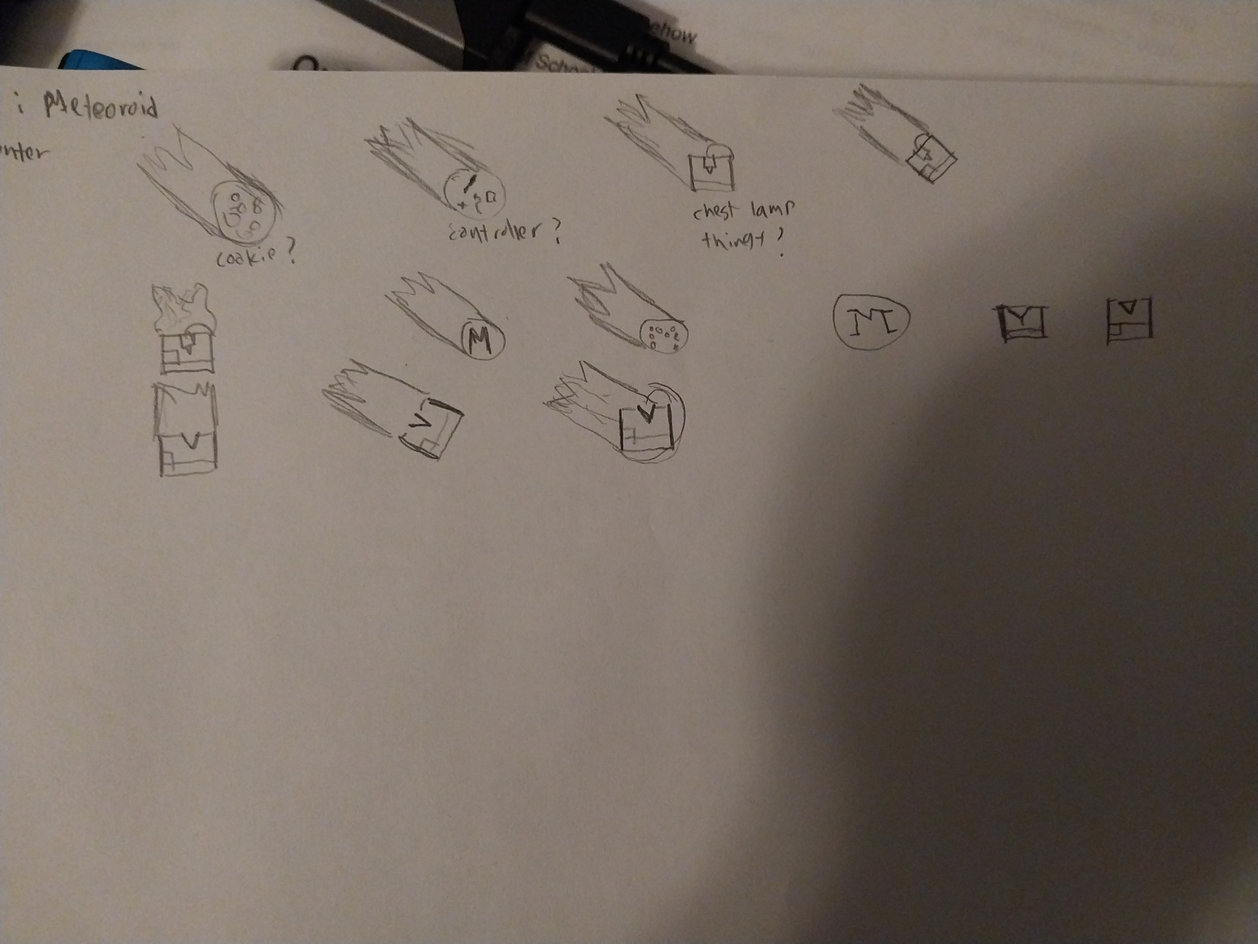
Time : 30min
Back at it - Feb 25, 2025
Okay, I’m back at it today, starting actual design work! I took my time creating a configerable vslot beam part that can change to any length on demand. I also assembled the base rectangle for the bottom.
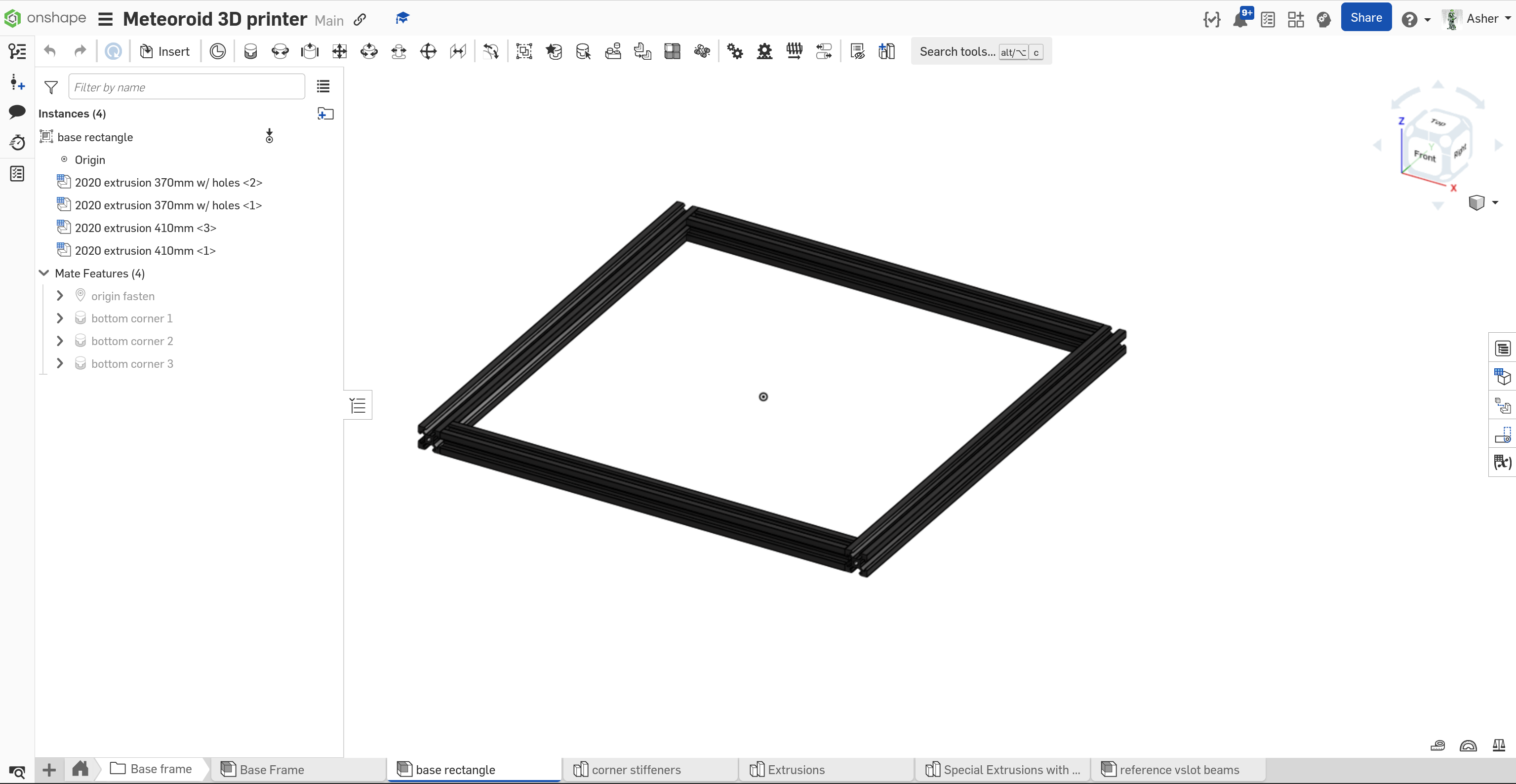
Time: 1 hr
More ideas - Feb 4th, 2025
I decided that for rails I should instead go with West3D Berserker MGN12 rails, they high quality and from my favorite supplier
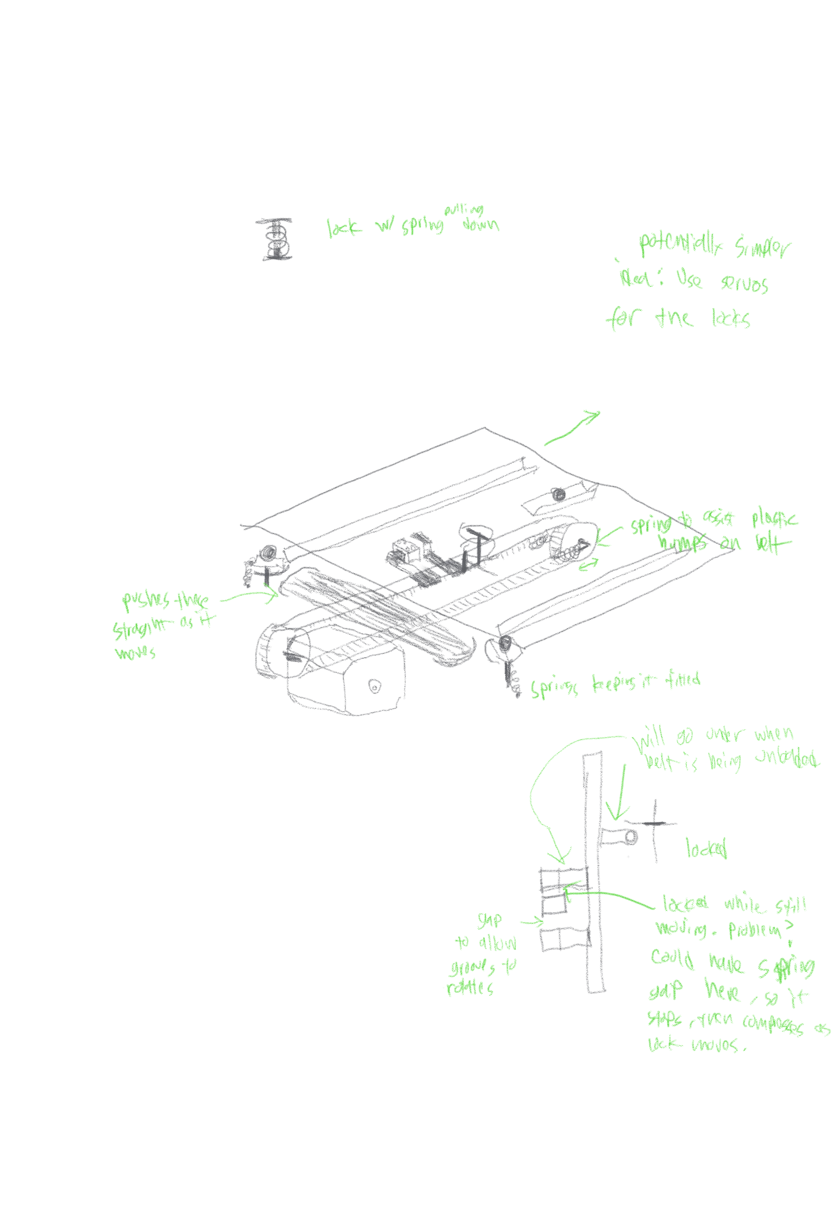
I had a greate idea for a bed ejection and combo scraper system for my printer using one motor. Basically it is a belt drive that at one end pulls the scrapper across the bed towards the front, but if it reverses it disengages and springs back, starting to push the bed out towards the back. There would be a robot port at the back to handle the bed and transport it to storage somehow.
Bed Options:
- 3d Printer bed, G10
- Laser bed with metal heat fins
- CNC Steel bed
- Pick & Place bed with a camera and part alignment jigs
There are also additional slots for toolhead accessories around the top of the printer that would have to be swapped automatically. I’m not sure the best way to replace accessory bays with an automated robot, since its difficult to reach inside the printer.
Accessory bay options:
- Nozzles for PnP head
- Feeders for PnP
- Klicky Probe
- Waste Material Ejection for color change and cleaning
- Revo hotends
- Camera mount
For the toolhead there are 4 slots for different active heads, but many more toolheads will likely be used, and I want them automatically loaded by some robot from storage. I’m thinking of having an extension arm that locks and grabs the toolheads the same way the printer carraige would (in towards the printer), but it would then drop down, go under the frame beam, and be encapsulated into a driving robot to take it to storage.
These robots would be completely independent of the manufacturing machines, they are driving robots with mechanum or swerve base capabily of transporting parts to storage or between machines easily. These carry Heads, Beds, Accessory Bays, Input Material, Output Material, and whatever else I decide should be automatically changed on the fly.
The head and bed should have 2 communication lanes and 2 high power lanes to have maximum flexiblity (if I wanted cameras on the parts for example). It is assumed that CAN bus and or USB 3 are used for high reliability.
Time: 30 min
Cont. Part Research - Feb 3rd, 2025
I added a few parts to my list. First up is the motherboard. I will still be reusing the BTT Octopus Pro for the printer, but for the BOM I decided to switch from the SKR mini E3 to a SKR Pico, which is a cheaper option that provides virtually the same functionality.
Since this is a modular industrial 3D printer, I will be having a tool changer with 4 slots. Without the Octopus I have, this would be impossible on normal motherboards. Even using the big motherboard, I would have big problem routing cables for many different toolheads. My best choice is to have a toolhead board that simplifies wiring, and for this I want the BTT EBB 36
I have also decided on the motors: LDO Motors 42STH48-2804AH. These are part of the Super Speedy lineup, and are high temp, high current 1.8 degree motors.
For the motion system I want to use 350mm Mitsumi Linear rails (3 of them) top mounted, and Gate belts
Additions:
- Motherboard on BOM: BTT SKR Pico
- Klipper Host: RPI zero 2 w or a spare SBC I have
- Toolboard: BTT EBB 36
- Carraige CoreXY Motors: LDO 42STH48-2804AH(S55)
Time: 1hr
Part Research - Feb 2nd, 2025
Today I spent several hours researching parts for my 3D printer that would deliver high performance and fit relatively in budget. I am planning on tearing down a CoreXY printer I already own and redesign from scratch. Some of the parts like the Ender 5 frame can be reused, so the price can be lowered for my prototype. I will still include the total cost with every part I have used, but the price I pay will be lower.
I new right away that the hotend had to have no compromises, so I started looking at hotend similar to the Rapido. I ended up finding the Triangle Labs Rapido ACE, which appears to be the newest and best in the rapido clone lineup. I also considered other hotends like a Bambu Lab or clone. The bambu lab hotends are nice and cheap, but I think they are limited for super high speed printing. They are also proprietary. I spent awhile pondering the Phaetus Dragon UHF hotend for awhile, another popular choice. I decided that it was a decent option, but the Rapido hotend had the highest capability. This took most of my research time
For the extruder I am going to go with something I know is stable and strong, the LDO Orbitor 2.0 extruder. This has been running on one of my printer much more reliably than the previous sherpa mini, and I haven’t found another extruder that balances price and extrusion force and weight so well.
I also briefly considered Smart Orbiter 3.0 all in one due to the lower price, but this didn’t have a super good hotend.
For controlling I know I need something cheap that can support klipper and has TMC drivers. The community disposition seemed to be towards the BigTreeTech E3 v3, so I threw it in without much consideration. The BOM will include this, but in reality I will be reusing a BTT Octopus Pro motherboard from the old printer build, it is super nice and I don’t want it to go to waste
I want to use some quality stepper motors, so I will use LDO motors for the carraige, and some cheap motors for the Z- axis
Summary:
- Hotend: Triangle Labs Rapido ACE
- Extruder: LDO Orbiter 2.0 with 36mm pancake motor
- Motherboard: BTT SKR mini E3 (my build will use BTT Octopus Pro)
- 2 Nema 17 motors from LDO 42STH48-something
- 2 nema 17 Ender 3 z-axis motors
Time: 4 hrs
Concept - Feb 1st, 2025
The basic concept is this: A desktop machine with plug and play heads and beds. Chain these together and add robot carriages in between and you got yourself an awesome factory that can fit in a bench. This is an opensource project. The cost of the entire system will likely be several thousand dollars, with the main machine limited to $300 budget. I aim to lower the cost of a complete industrial system as much as possible.
The head and bed have 2 communication lanes and 2 high power lanes. It is assumed that CAN bus and or USB 3 are used for high reliability.
Time: 30 min