Mu Draconis
mu draconis
Made by : William respository link: https://github.com/WilliamPrime/Mu-Draconis
i have a 3d printer :D total hours so far: arround 60
pitch, make a polar 3d printer, not because its practical, but because its something different :D
i would be taking inspiration from this, but making it more functional https://www.reddit.com/r/3Dprinting/comments/16dsugh/received_a_ton_of_constructive_criticism_on_my/
i want this to look very clean, probably be control only via klipper, no phyiscal controls
im still deciding if i want to have a heated bed or not, or if i want it to be a “fast” polar printer and use a nema 34 on the bed or something like that
the gantry should also be fairly easy to remove for shipping, so xt-60 connectors and other jst things will be needed to make sure that all the cables are easily detachable
also had the idea of having suction cup style things on the base so it sticks down to a table, its just a funny idea
so far i have some parts ive found and extracted out of dead 3d printers:
- ras pi 4 8gb
- big tree tech skr mini E3 (the mosfets for heaters and fans are dead, but stepper drivers still work)
- voron klipper expansion board
- hardmount v6 style hotend
- 70w 24v heater cartridge
- 40w 24v heater cartridge
im hopeing i can use them without them counting towards the cost of the BOM
first two days of planning, around 4hours into it:
ive decided quite a bit about my printer i want to use a 250mm round heated bed i want to use a slip ring so i can get power to the bed and have a heated bed on this printer i plan to use linear rods and linear bearing for both the x and z the x will 100% be belted im still deciding if the z should be belted or use a lead screw i also started to model out some of the components i plan to use in fusion 360, such as the bed as a starting point however it appears the technical drawing from the manufacturer REALLY isnt accurate
current rough BOM as of starting
| Part name | price | notes |
|---|---|---|
| 250mm dia hotbed | £13.89 | |
| ras pi 4 8GB | already owned | |
| semi broken btt skr mini e3 | already owned | dead mosfets, but stepper drivers still good |
| klipper expansion board | already owned | to compensate for the dead mosfets on the mainboard |
| nema 17 motor with leadscrew | £13.49 | 320mm leadscrew might trim down to 200mm |
| thermal fuse | £1.85 | 100c thermal fuse to prevent run away on the bed |
| nema 23, 76 mm motor for bed | £18.69 | overkill, will prob change to help budget |
| slip ring | £13.02 | 3 channel, 30A per channel 22mm dia |
| bicycle bearing | £1.46 | cheapest way to get a large bearing for bed (41mm id) |
| C14 S8B3 power panel | £1.36 | |
| mellow sherpa mini kit | £30.39 | good, light extruder |
| gates 2GT 6mm belt 1m | £4.79 | |
| 20t pulley x2 | £3.30 | |
| 20t idler x2 | £3.10 | |
| LDO-42STH48-2804AH-R | £26.09 | the goat of stepper motors, could use a cheaper 42STH48 2804AC-R instead for more torque i think |
| Meanwell LRS350 | £23.59 | |
| pt1000 thermistor | £4.53 | overkill but i maybe want high temp, no clue |
| 250mm bed surface+magnet+sheet | £15.39 | |
| end stops x3 | £3.20 | |
| mosfet for bed/heater x2 | £3.28 | |
| 200mm 8mm dia linear rod x2 | £5.76 | |
| 330mm 8mm dia linear rod x2 | £6.32 | |
| Fushi LM8-UU/2pcs | £9.79 | |
| Fushi LM8-LUU/2pcs | £12.29 |
08/02/2025 (arround 5 total hours)
put another 2 or 3 hours into sketching out how im going to get this to work finally managed to start getting stuff modelled in fusion 360
the belting seems daunting but i recon its going to be nice
ive struggled to try and model the bed as almost all of the technical drawing on the aliexpress listings are horrible
15/02/2025 (arround 13 total hours)
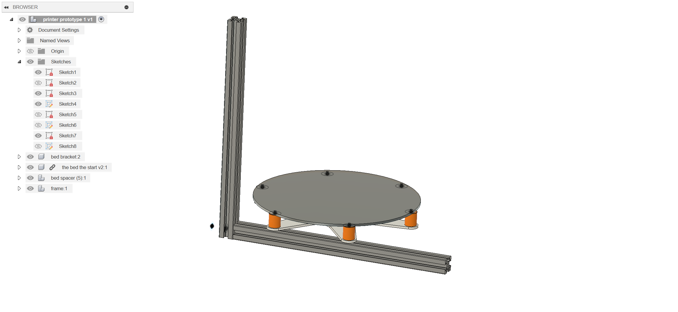
made alot more progress ive been modelling the respective components im going to need for my build ive also started to model the assemblies so i can start combining them
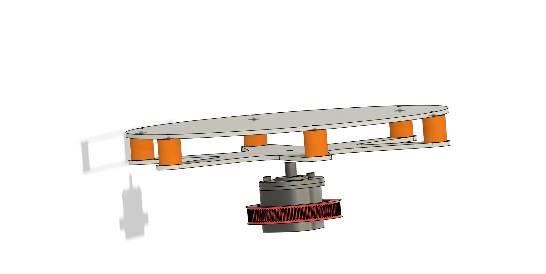
ive decided to start with the bed because i think the bed will be the biggest challenge to make the bed is probably my biggest challenge because i need to deal with belts to rotate the bed, and also belt tensioning for that, but i also need to deal with getting power to the bed as i would like to have a powered bed, for that i also need to deal with the slip ring the solution i think i have come up with is 3d printing a custom hollow pulley/sprocket that will attach to the bed, that way the slipring can be on the inside of it and still deliver power
here are some images of the CAD that ive started to hobble together
18/02/2025 (arround 18 total hours)
started working on belt tensioners
 they were surprisingly tricky to design
but im hoping maybe if i go all belts then i can reuse the belt tensioners across the printer
they were surprisingly tricky to design
but im hoping maybe if i go all belts then i can reuse the belt tensioners across the printer
it feels quite voron 0 inspired, but that was what i was inspired by :D
im honestly not sure what the time frame was, probably arround 23 hours total time
anytime i was at my computer doing nothing i would try and get a lil bit done so i didnt really get much big stuff done but still stuff changed
07/04/2024 (arround 26 hours total probably more)


realised how much easier it would be if i just went the route of desiging some parts seperately then importing them into the main file i can definetly say it took me way to long to get that basic belt tensioner working :( but oh well
07/04/2024 arround 31 hours in
some more jumps got stuck as one of my parts was 0.2 degrees misaligned and that really threw me off BUT I FOUND THE ALIGN TOOL
i had been using components to make everything work
but i realised how much it helps me to focus when i make things in smaller files where i can and combine them into a bigger file later :D

im doing this while sleep deprived
so im still working on the printer
made some overall progress on tidying up the hierarchy of mess in the component tree

 made alot of work on getting the motor for the x axis actually mounted
i think it maybe gets easier and harder from here
from hearing from other people the tool head might be hard
but i also dread the weird bearing thing i made for the rotation axis
made alot of work on getting the motor for the x axis actually mounted
i think it maybe gets easier and harder from here
from hearing from other people the tool head might be hard
but i also dread the weird bearing thing i made for the rotation axis

realised that i needed more material there to propperly support everything 2.5mm of pla didnt really feel enough also wanted extra thickness there so that i can use heat sets to mount my hot end stuff :D
another update
started and “finished” on the hotend


 i was anticipating alot more difficulty designing the ducts for the hot end fans than i actually encounter
however i did encounter some difficulty since my hot end is going on the same side of my carridge as my belts, im encountering issue of how to mount the hot end without sacrificing rigidity, i believe it shouldnt be too hard to just have the hot end on the other side, and then just flip the bed onto the other side of the bottom 2020 extrusion, and that should then fix the issue without needing any extra hardware, right now im trying to get the printer functional so i can refine the cad more and fix some the issues that can be fixed without needing more hardware.
you can also see the fan ducts are aligned with the centre of the nozzle, also not intentional :( sorry
this ended up being really spaghettic like, im not sure how to use mark down files properly, you can probably tell updated BOM is here https://docs.google.com/spreadsheets/d/1IZOwHB4fpJywedBBVYQKaOOAUHnNrE4fSURzN-7t6E4/edit?gid=0#gid=0
17/04/2025 BIG changes and a bit of a write up and summary that is long due arround
spent the last 10 hours working on the 3d printer polishing out all of the missing bolts in the cad and making a copy of the cad, the removing each body until there was nothing left to get a good BOM that is actually complete and accurate :D
so, going through some of the issues that ive faced and problems as i think that is what i should probably put here, the end result is nice and all but its the challenges we faced along the way and all of the little decisions we make that really define a project
the first issue i really faced in the project was the slip ring for powering the bed
i realised i needed both power for the bed and some sort of bearing that was big enough for the slip ring to go through the bearing
i reallyyy didnt like the look of how expensive beaings costed
so my solution was to 3d print a bearing
i found a couple of videos that served as a good starting ground as to how to make a bearing
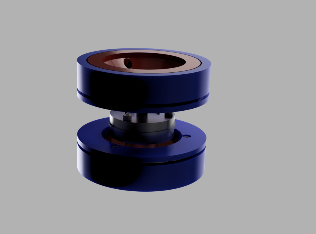
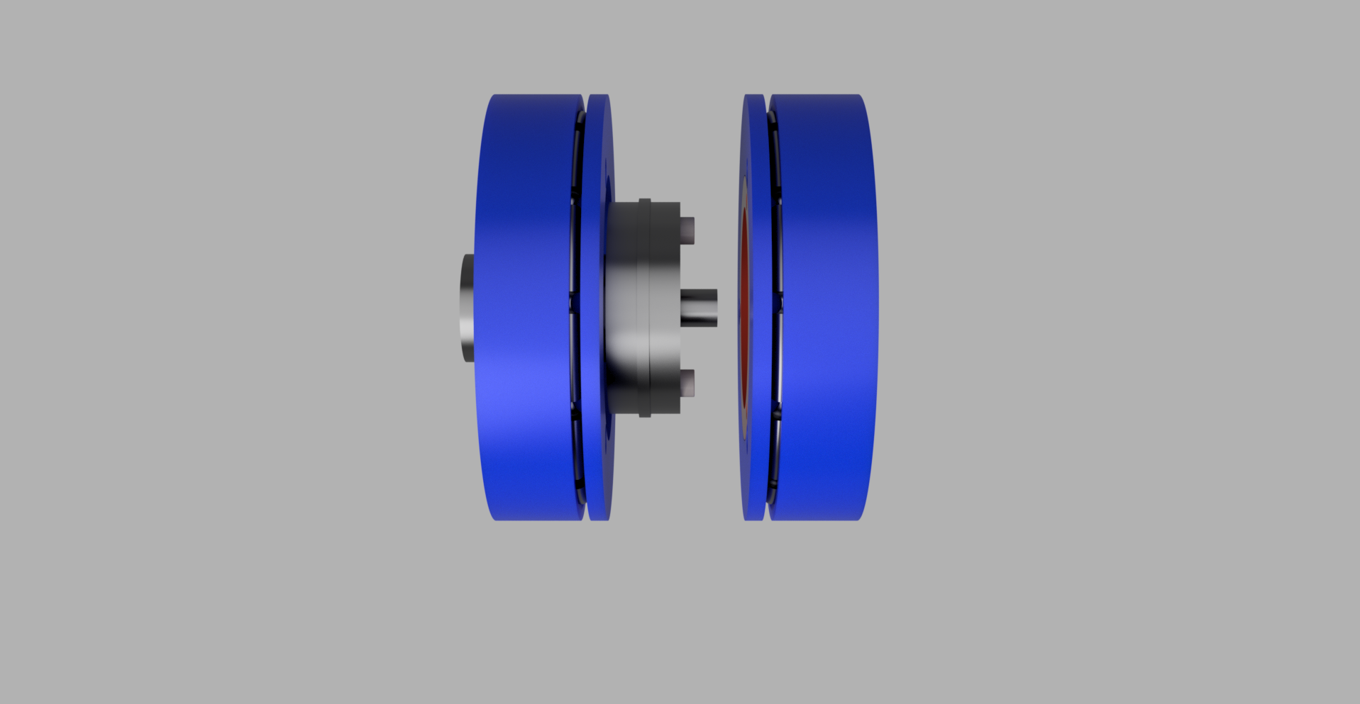
i also decided on using a thrust bearing as those have good axial and radial stability which i thought would be usefull
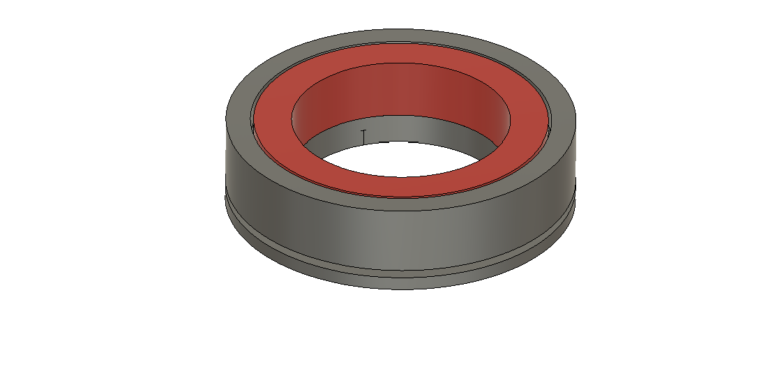
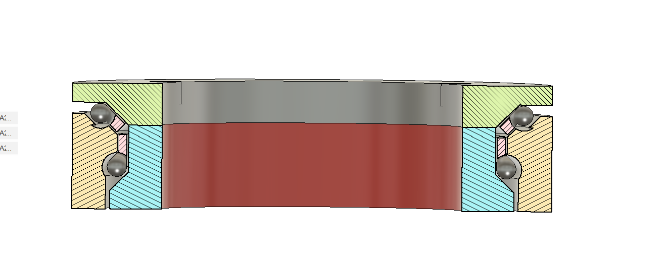
i then stacked two of those on top of each other to try and get a bit more stability as i REALLY dont want my bed to be wobbly that would kill my print quality so that gets us to about here
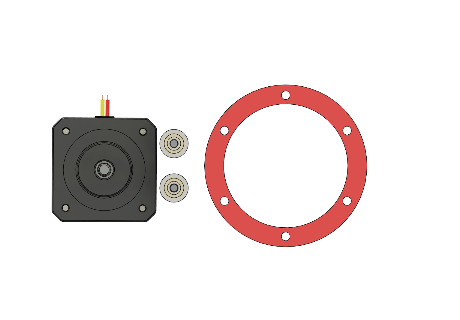
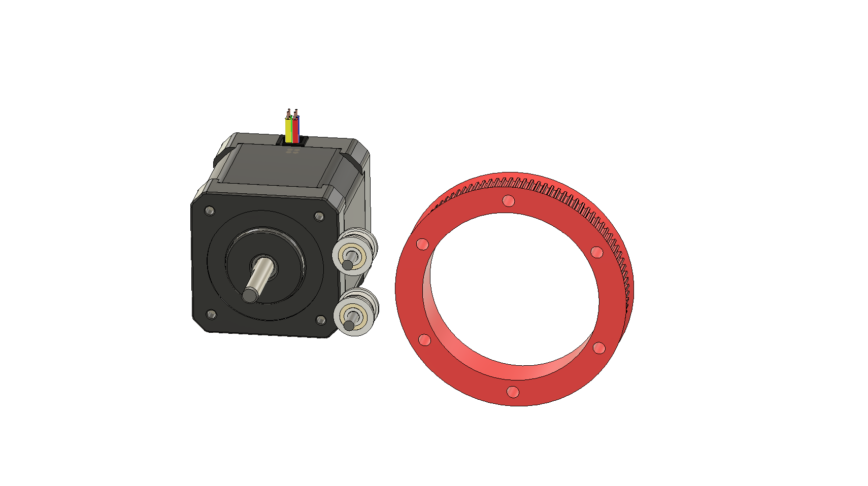
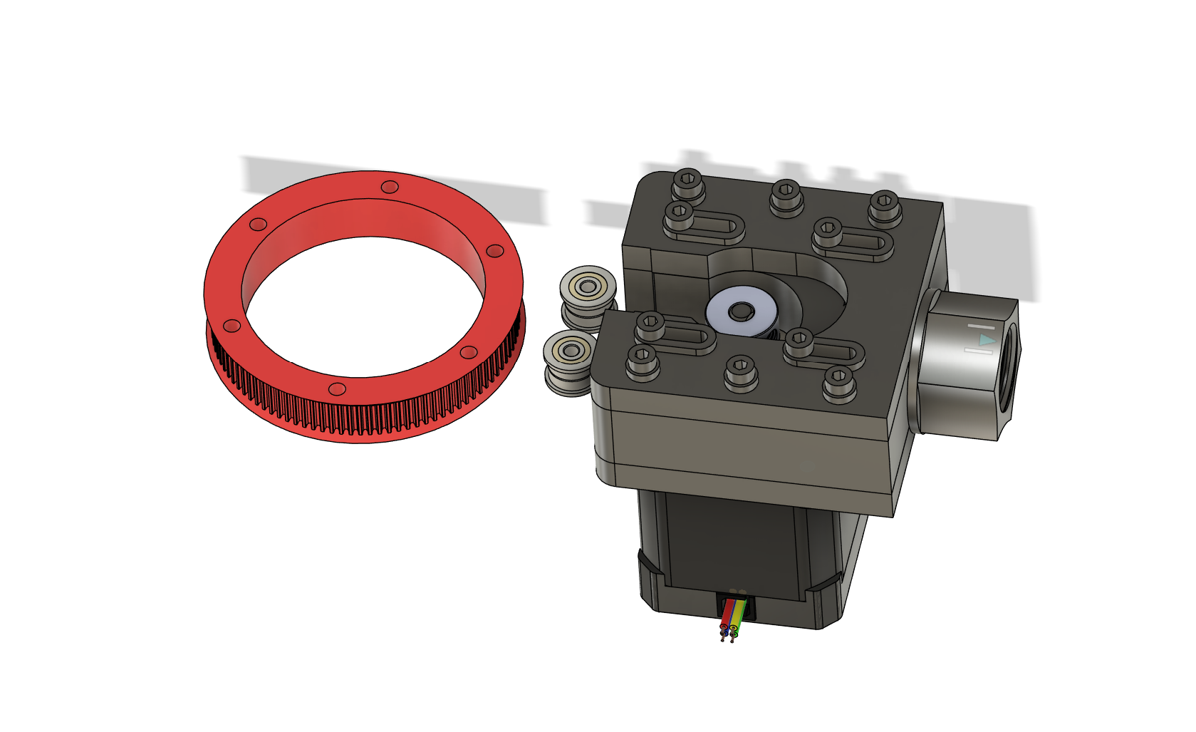
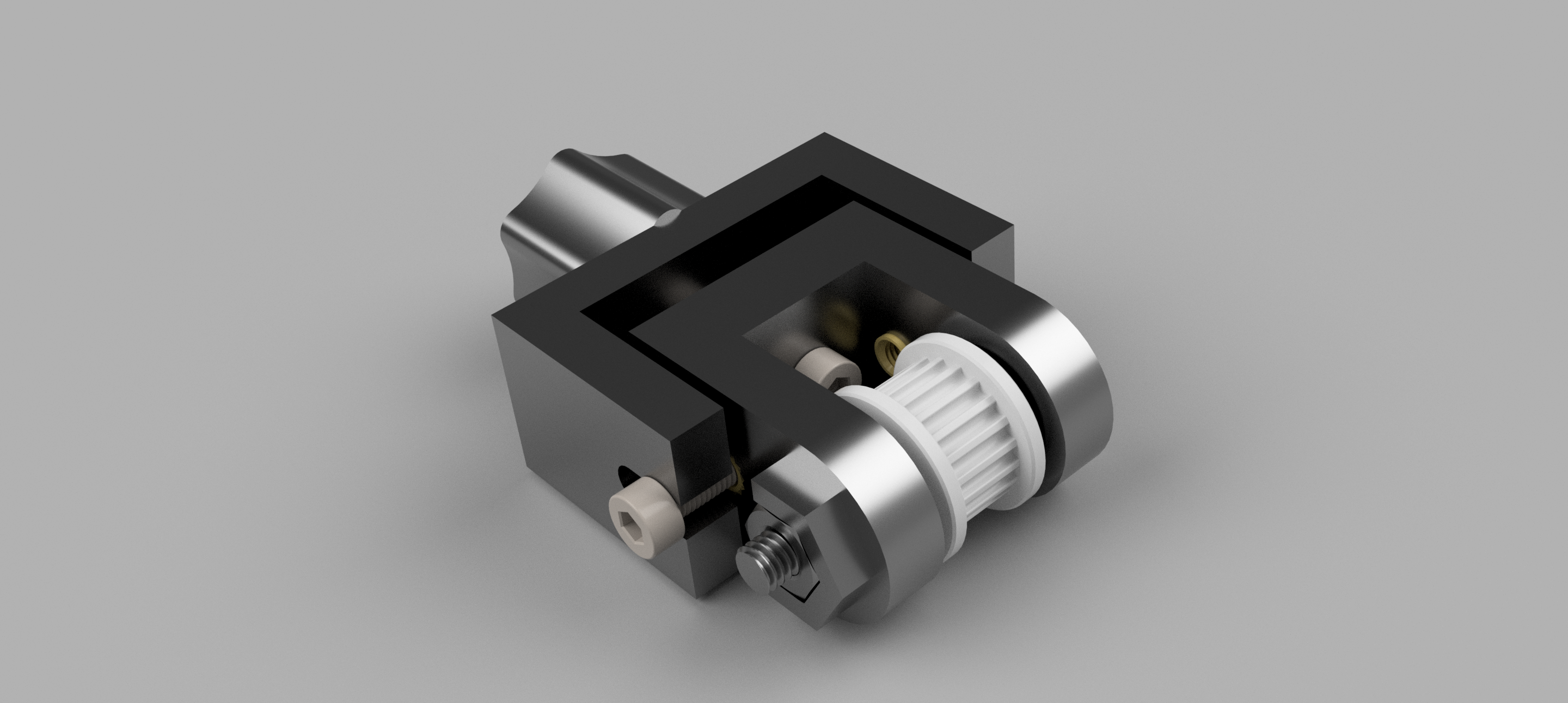
my next task was to try and transmit the actual mechanical power that was going to turn the bed so i want to try and have some sort of “gear ratio” since i dont think i need the max speed of the nema 17 motors that i wanted to use however to spin the bed it think i need more torque so my solution was for the bed to have a sprocket that has a more teeth, then the motors has a pulley with less teeth
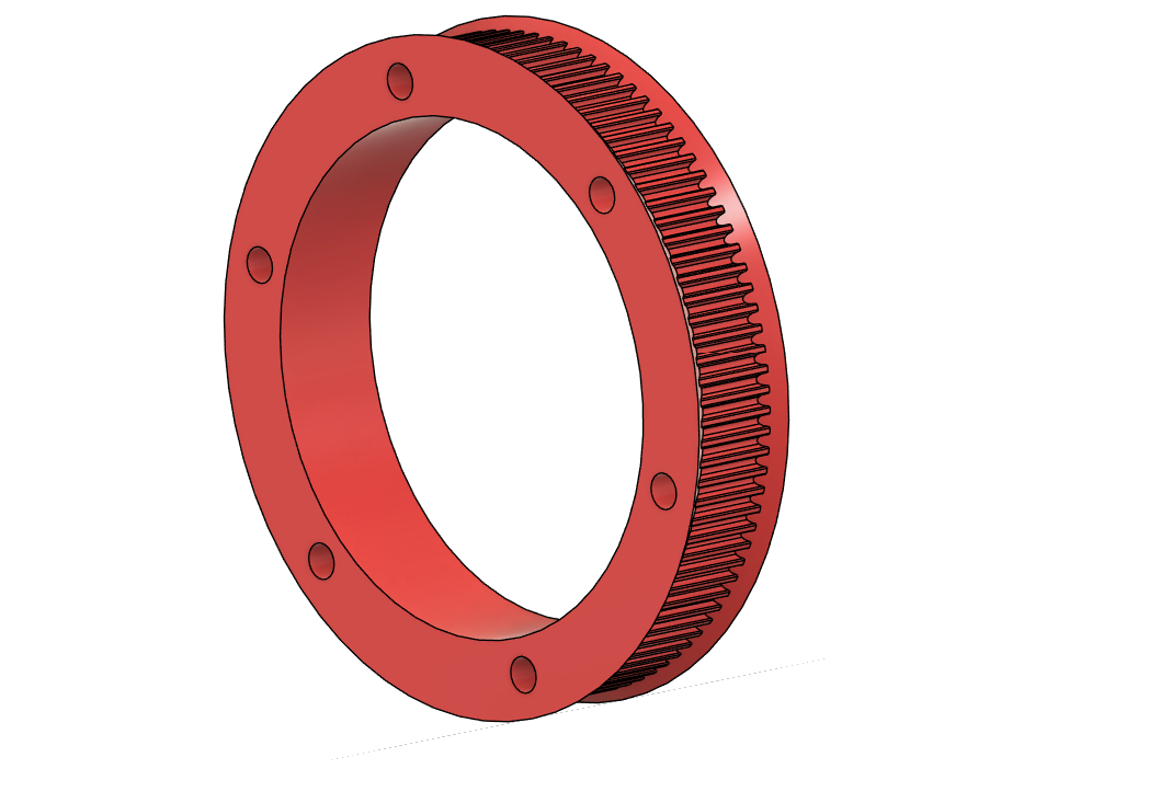
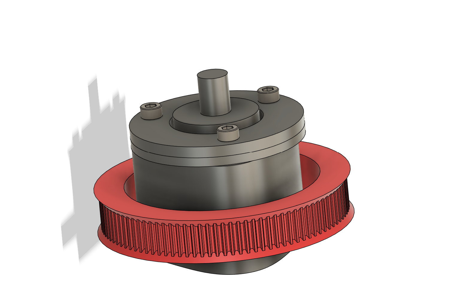
now the issue is trying to get a pulley that has something like 80 teeth out of metal that would be big and expensive and i dont know how i would mount it so why not 3D print it i thought? WHY NOT 3D PRINT IT so i set out on a journey to try and model a pulley with a custom ammount of teeth then some youtube following later and some thinking you get this :D (i really dont know why this bit started to feel like a monologue from something, its fine im just tired)

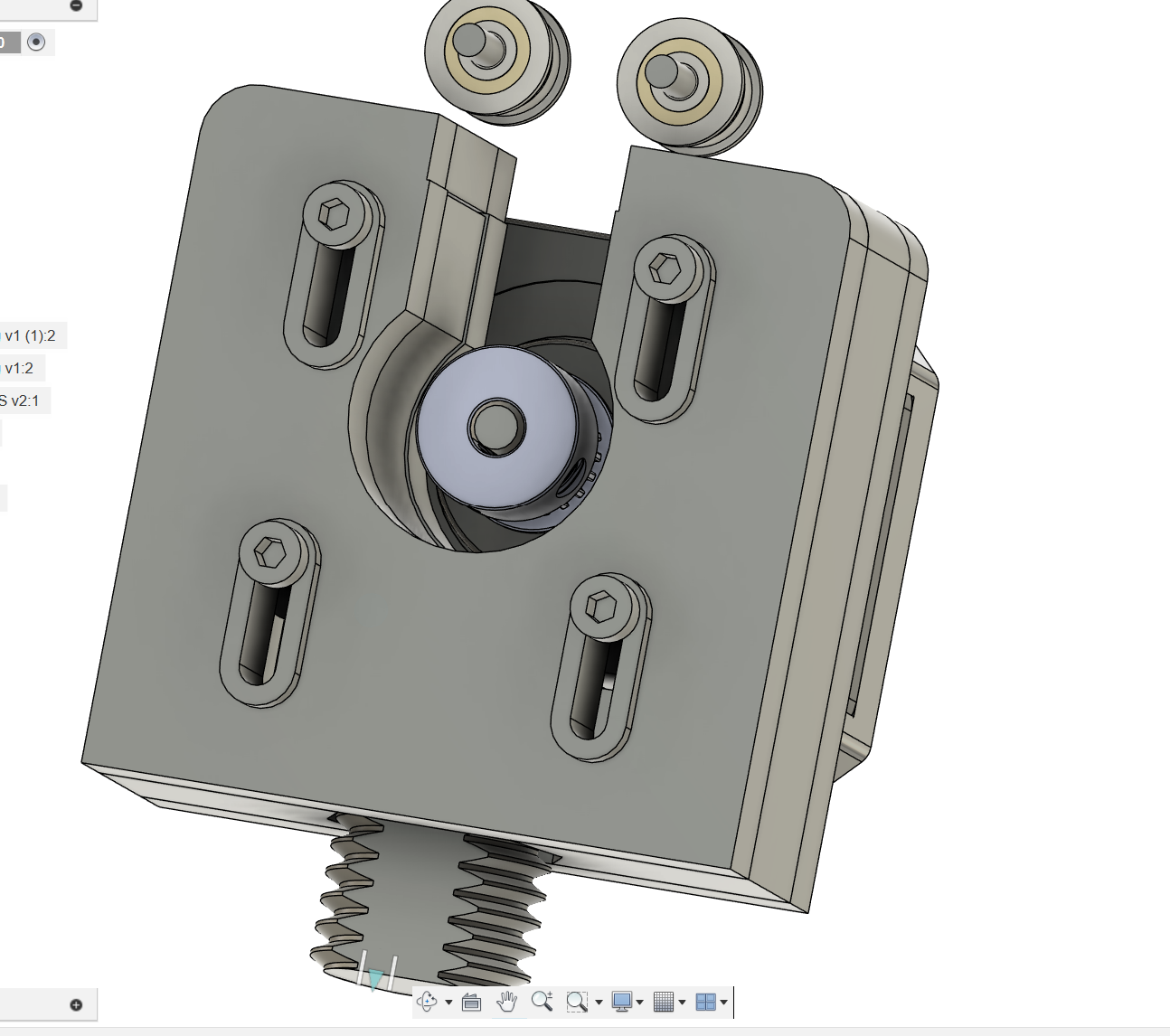
now i just need to design a motor mount that has a tensioner aswell because i will need to use a closed belt loop i have a v0.1 (im proud of this i will say it now and i will probably yap and say it again) and i was inspired by the way they did it so i set along desinging the mounts the way i wanted to
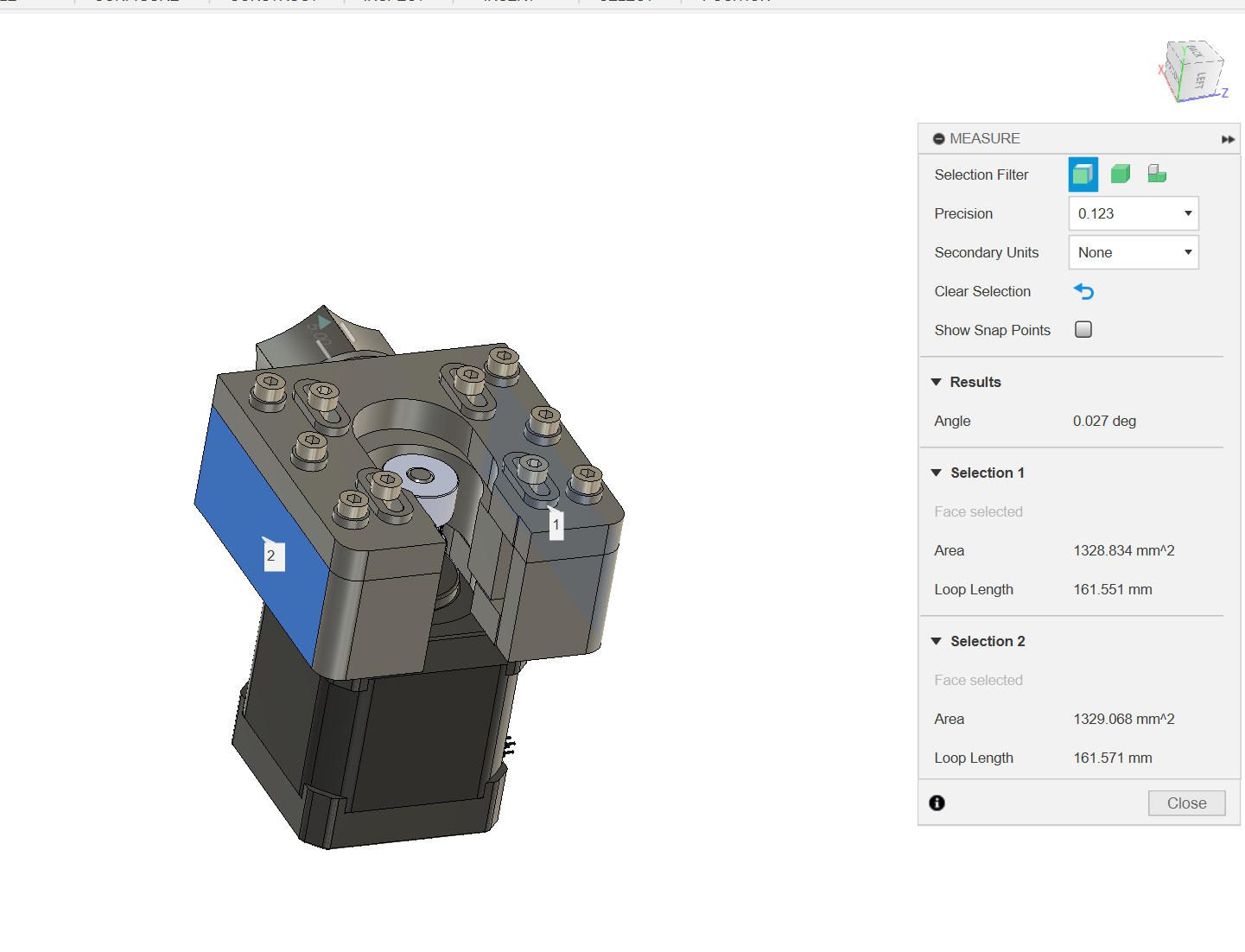
here you can also see my stupidity in full force i didnt use contraints properly and as a result there is a tiny angle between the two sides of my tensionser i didnt realise this until ALOT later in the design
i did think something was off when i designed it however my normal checks for how square the coners for something are, are check the opposing sides are equal then check the diagonals are equal
since the angle was so tiny the diagonals were so closer that fusion said they were the same :sob :

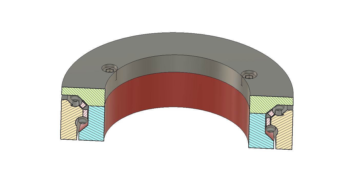
so looking at what i have so far in that assembly it looks something like this i also added in a pair of bearing to help the belt contact more of the pulleys teeth at any one time since the pulley will be 3d printed after all
i also 3d printed a test of the pulley to see if the teeth mesh properly with some spare gt2 belt from my V0.1 (i told you i would mention it again) sadly ive managed to loose that :sad:

 i also added on some little sticky out bits to the bearing that i hoped to later use for mounting to the frame of the printer
https://hc-cdn.hel1.your-objectstorage.com/s/v3/0fb4699f730b00b6d34ee98721cad8a2cb5b5bb7_aaaa.png
i will come back to the custom 3d printed bearings again later and how they should be assembled because i think thats probably a good idea
my next step was to start desinging a frame

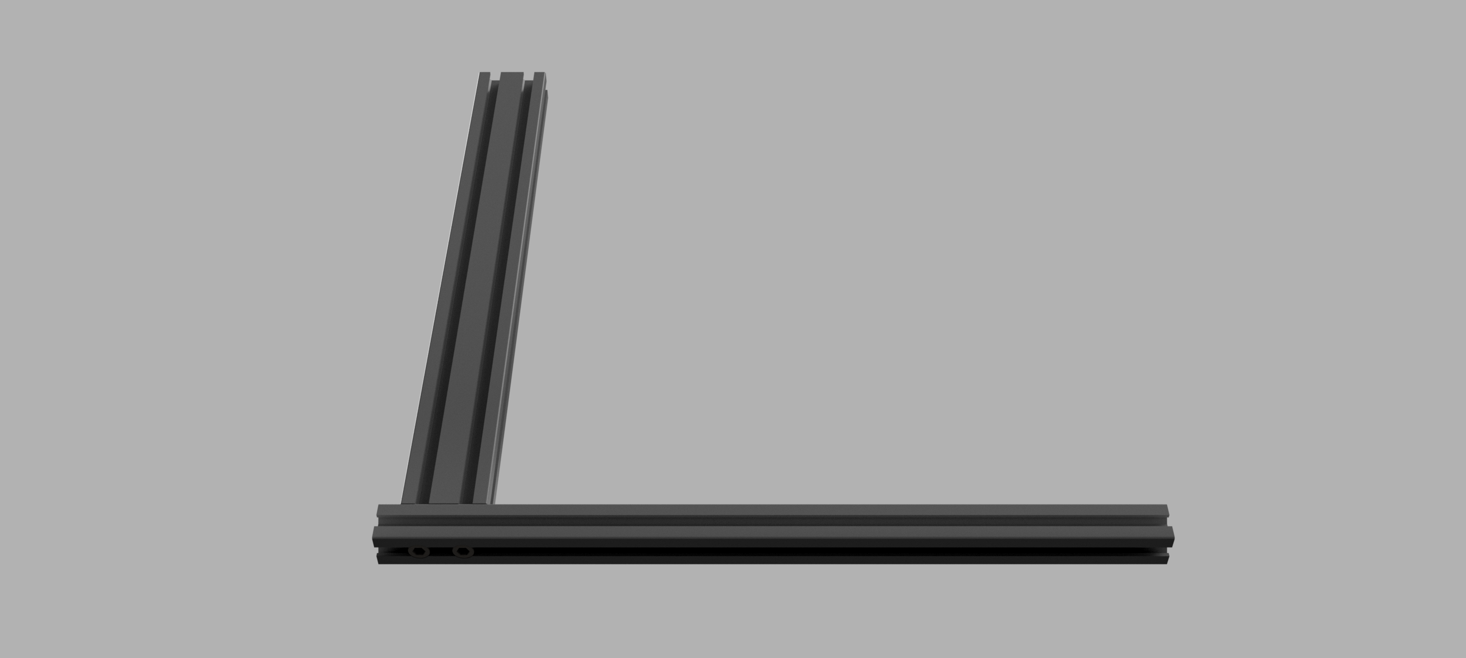
and then after that some feet so it doesnt fall over the timeline is a bit messy here but i think it would be better to have them here with the frame, it just makes sense that way
the design of the legs are pretty simple just doing it by eye so the printer is stable enough im going to have the powersupply at the bottom later , and the priter should be pretty stable as any wobling would be parralel to the bottom extrusion
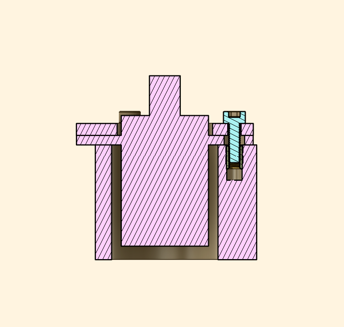
the feet are also two part to make them easier to print then using a heat set and a screw to join them together


chronologically, i had started to work on getting the bed mounted however i wasnt sure exactly where the hotend was supposed to end up so it ended up being a bit overwealming and that lead to me getting lost quite a few times while trying to go that route so instead i started work on the Z axis with hopes of then working on the X axis, and then the hottend so i could actually see where my nozzle was going to end up
my first step towards a Z acis was getting something to hold to linear rods and for that i designed this little thing that could be used for the top and the bottom of each rod nicely securing them to the extrusion :D

and then adding in the rods,

then got a nice little carridge going :D

and realised i needed a way to get the belts to actually be gripped onto my soltion, just weird grippy thing :D with teeth or the blet profile, whatever you want to call it

then with another chunk of messing arround i got the belt modeled in with all the teeth, i dont exactly know wher i deceided to modeling in the teeth, i didnt do it for any of the other belts, so now it just looks a bit odd
BUT YEAH i got the belts modelled in and then i also got a nice little motor bracket modelled in with a motor and pulley i got from grabcad very nice so far

thats the Z axis done
good time to also mention breaking the chronological timeline here but i designing a belt tensionser while making the x axis with the idea being to use it wherever i need to tension belts so that was also used here to avoid the overwhelming mess of what the fusion file was at this point, i designed the idler in a different files and then imported it into the main file
you do have to love the way i designed the bracket that holds the tensioner it’s HORRIBLE BUT IT WORKS you just need to tension the z before you mount the belt idler
 so actually the Z axis looks like this
first thing i did was quickly throw together a plate to finish attaching the X axis rods to the Z axis


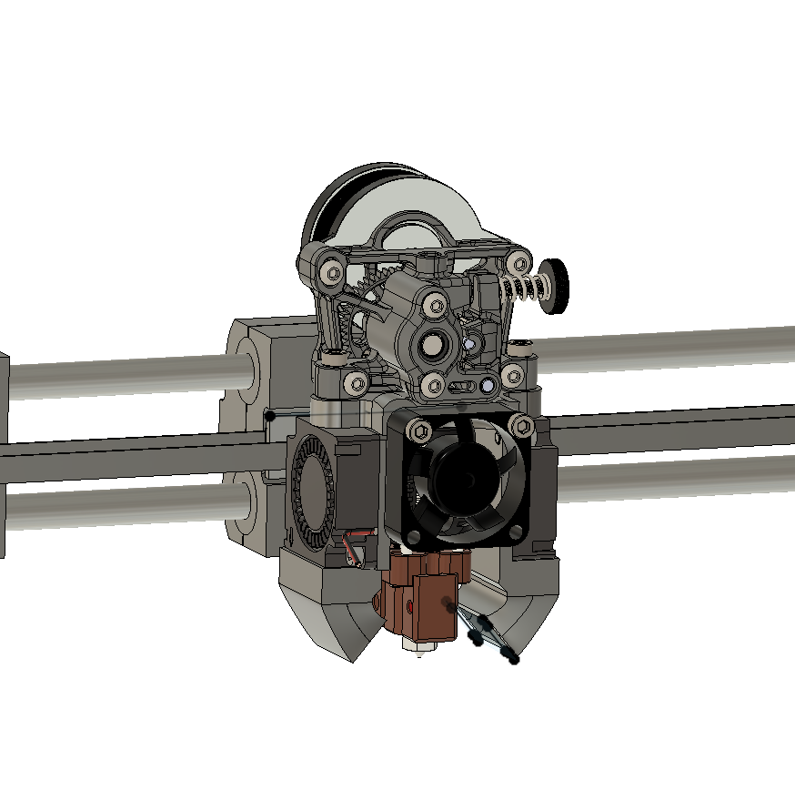
then that gets us onto the next bit the hotend, the fun fancy probably most expensive part of this whole thing i decided to save a good chunk of the budget, i was going to use the dragon HF hotend, with the mellow NF crazy volcano heatblock for this printer and i would take it off of my voron 0.1 (WOOO THE VORON V0.1 MENTIONED AGAIN), and use the stock hotend that came with the voron on the voron meaning this printer gets quite a nice hotend :D i also wanted to use a sherpa mini extruder as i have found them to just be a nice extruder that is relaiable, and can handle pretty much whatever material you can throw at it ive printed TPU with it so its pretty nice :D here is a little render of the hotend


fan mount for this was super simple i do love the simplicity of it :D

add in some ducts


this is probably the least gracefull, and most confusing part of the entire printer
the bed
my first step was to create something to mount the two bearings to the frame
its not gracefull
but here is the little mount i designed
 the next step was actually joining the two bearing and the pulley together to get it all working as one nice big peice

i also realised that i need something to stop the stationary part of the slipring from just spinning
since there wount be much force on it AT ALL , i could make it really quickly and not worry about strength, which gives us this little cute thing

then for the electonics
i threw together a little mount for the skr mini
and the ras pi i have allready has a heatsync and i dont really want to take it out of that
so im just doulble sided taping it to the frame :D
then the mount for the skr mini will also be getting the double sided tape treatment


i also had a nice little solution for how to mount the c14 inlet i first designed a thing to hold the c14 inlet and then just joined it to the same leg that has the pi and skr mini just on the other side


but i wasnt quite sure where to put the psu
since the vertical extrusion has stuff all over it
i cant mount it to that
the horizontal extrusion has stuff
and then it just seemed really hard to find anywhere that it could actually mount to
but i found a nice little place to nestle it


the soluation i managed to come up with
was to raise the “feet” of the printer a little bit i think arround 4mm
and then it fits VERY snugly under the z motor with that extra clearance
and its right next to the foot under the vertical extrusion which gives me something nice for it to mount to
here you can see ive raised the feet to fit it, and then the holes that will let me mount the PSU
 and then with the psu it looks like thise

however the screw terminals looked a bit exposed

and i REALLYY dont want to accidentally touch live 240v ac thats not how i want to go out so i designed a nice little cover for the screw terminals to prevent me accidentally zapping myself

now that we are on electronics i should probably make an electronics diagram for this but im not sure if it needs one
so i will just write it out
240v comes in through the C14 inlet That then goes to the PSU so i have 24v for the rest of the printer
that 24v will need to power the: 2 heater relays, SKR MINI E3 V3, and kliiper expansion board
the motors all attach to the SKR mini the endstops all attach to the SKR mini thermistors attach to SKR mini
however because of the me having an SKR mini that has a dead multiplexer, meaning that none of the mosfets work i need to use a klipper expansion board to get mosfets to controll my fans and heaters my fans will connect directly to the klipper expansion board the bed and hotend however draw alot more power the bed could draw 150w and the hotend 80w im not confident the klipper expansion board can handle that much current , arround 3-6A so im using a little external mosfet board to power the bed and hotend the boards get power from the PSU but they get the signal from the klipper expansion board mosftets
random bits for the end almost forgot to make endstops so i came up with this cute little thing that fits on the the 8mm linear rods, as shown here :D


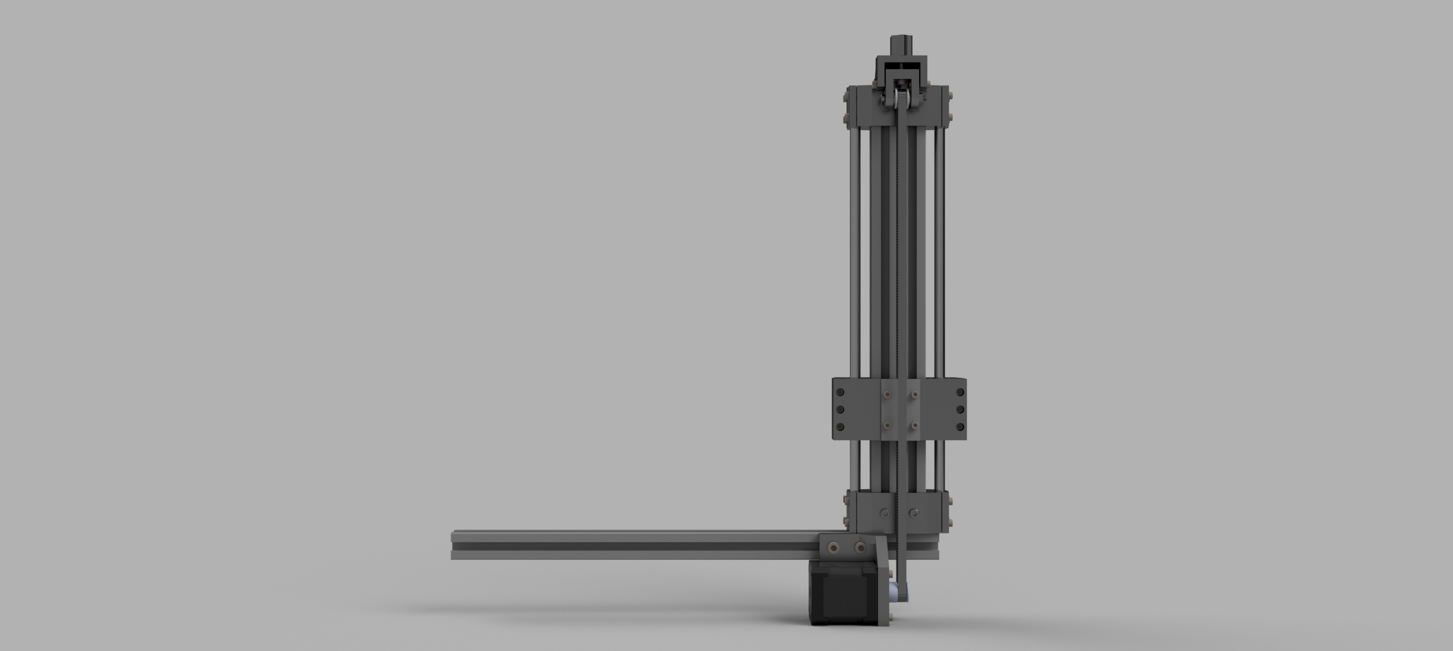
so that gets us to this nice render of the printer in what is currently its finished form :D


i have got some things i do want to improve, but those involve change the 3d printed parts not any of the hardware the list of stuff i want to make less bad are:
make the hotend mount more secure
better fan duct design
fix the 0.0027 degree angle on the sides of the bed belt tensioner thing