OrbeXY
Made by: @esemv
Repository link: https://github.com/esemv07/OrbeXY-3D-Printer
Total hours so far: 64 hours
- I have a 3D printer or will be getting one before March 21st
What Makes My Printer Unique?
Goals
- CoreXY Kinematics
- Under 280mm3 total size
- 100mm3 build volume
- Runs Klipper
- Pico MMU Compatible
- Remote Printing
Achieved So Far
- CoreXY Kinematics
- Under 280mm3 total size
- 100mm3 build volume
- Runs Klipper
- Pico MMU Compatible
- Remote Printing
Day 1: March 8th 2025
Reseach PCB CAD
-
I reseached materials and what would be compatible with each other while staying in budget and my size constraints. I decided on an Extuder (Obbiter V2.0), and a Motherboard (BigTreeTech SKR Mini E3 V3.0).
-
I found a potential option for a printbed. It is quite difficult to find one that is in the correct size (100x100mm) as most come in 120x120 for the smallest size. I have decided that for the PEI Plate, I will buy a bigger size and cut it to the correct dimensions myself.
-
I then designed a quick and simple PCB for the small Optical Endstop Sensors that I can use to keep the printhead in build area for all axes.
Research: +3 hours PCB: +1 hour
+4 hours
- I also researched different methods of multicolour printing and what would take up less space. Started designing a PCB for a Rotary Switcher Multi Material System, but then realised it would be to big for my printer size. I settled on using an MMU but I think I will design that last so I get the core mechanics good first.
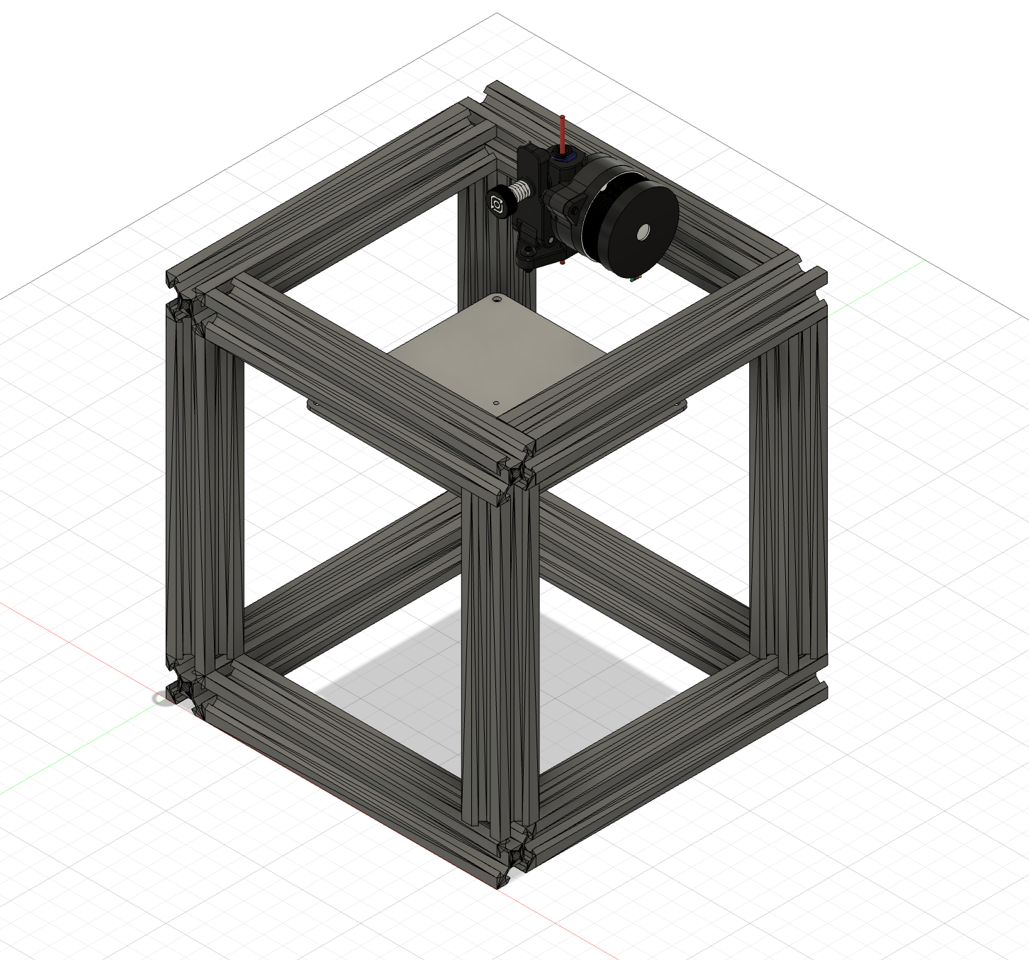
- Started a rough CAD model in Fusion of the frame to visualise the dimensions. I may change the 2020 Aluminium Extrusions to 1010.
Research: +1 hour CAD: +2 hours
+3 hours
Time Spent on This Day: 7 hours
Research: 4 hours PCB: 1 hour CAD: 2 hours
Day 2: March 9th 2025
Research CAD
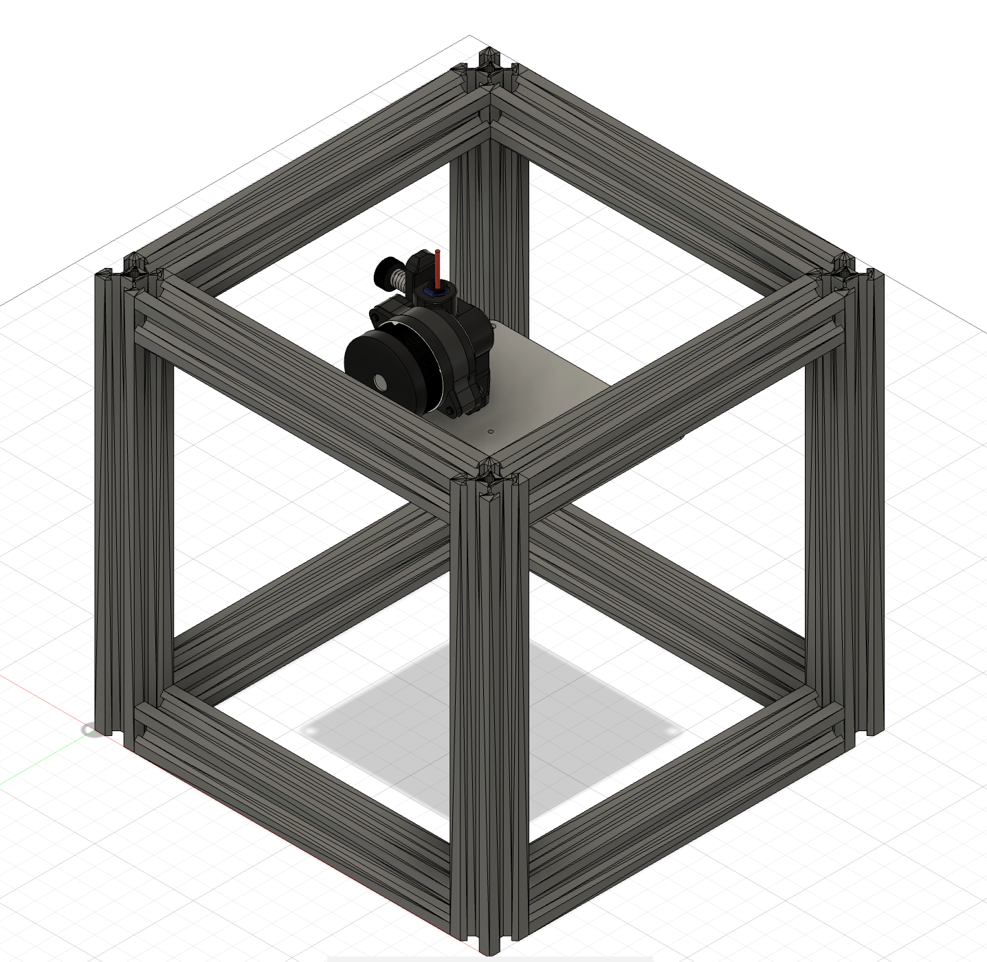
-
I reshaped the frame so that there was more space on the inside and it will be less confusing for physical connection when I build it. It is now 200mm3, using 8 x 2020 160mm Aluminium Extrusions and 4 x 2020 200mm Aluminium Extrusions.
-
I then researched power supplies - how they work, how to know what voltage, current, and wattage to use. I also researched different methods for the Z-Axis on a CoreXY printer. I figured out that due to the very small scale of my printer I won’t need to support all 4 corners of the build plate.
-
I also reasearched hotends and how to connect them to my extruder which is direct drive. I am going to design a 3D printable mount so I can connect my direct drive extruder (Orbiter V2.0) with my hotend (Short E3D V6 Hotend with PTFE).
Research: +3 hours CAD: +30 mins
+3 hours 30 mins
Time Spent on This Day: 3 hours 30 mins
Research: 3 hours CAD: 30 mins
Day 3: March 10th 2025
Research CAD
- I researched toolhead designs and what fans I could use for mine and how I could mount the extruder to the hotend.
Research: +1 hour
+1 hour
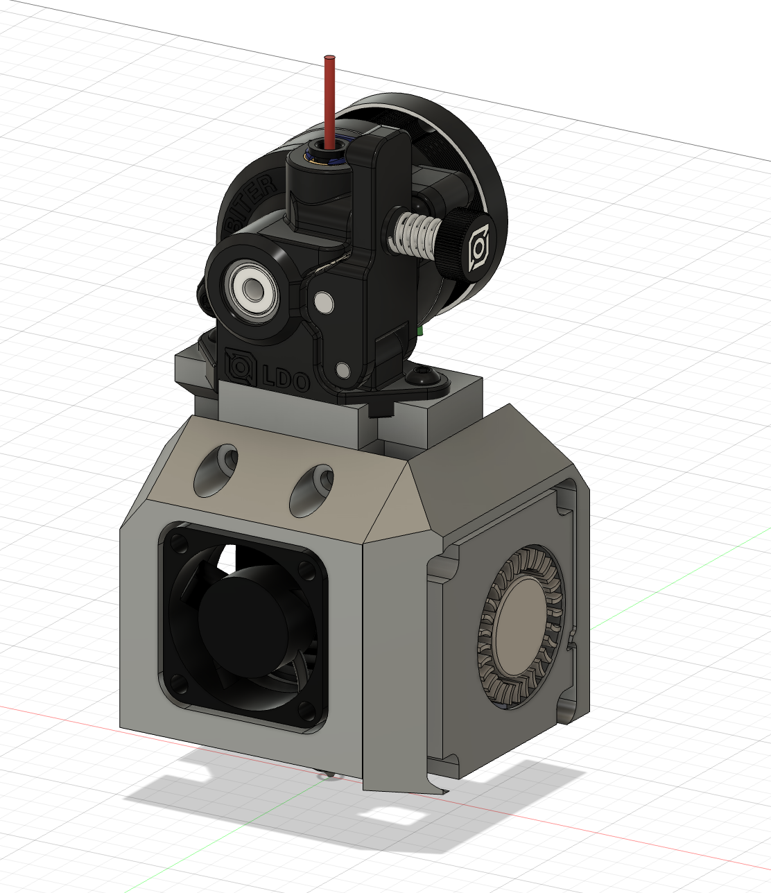
-
I designed the toolhead with different parts that would mount together using screws and heatset inserts.
-
There are 3 different parts: the part that mounts to the front of the hotend, the part that connects the axial fan to that part, and the part that mounts to the back of the hotend connecting the other fan and the extruder.
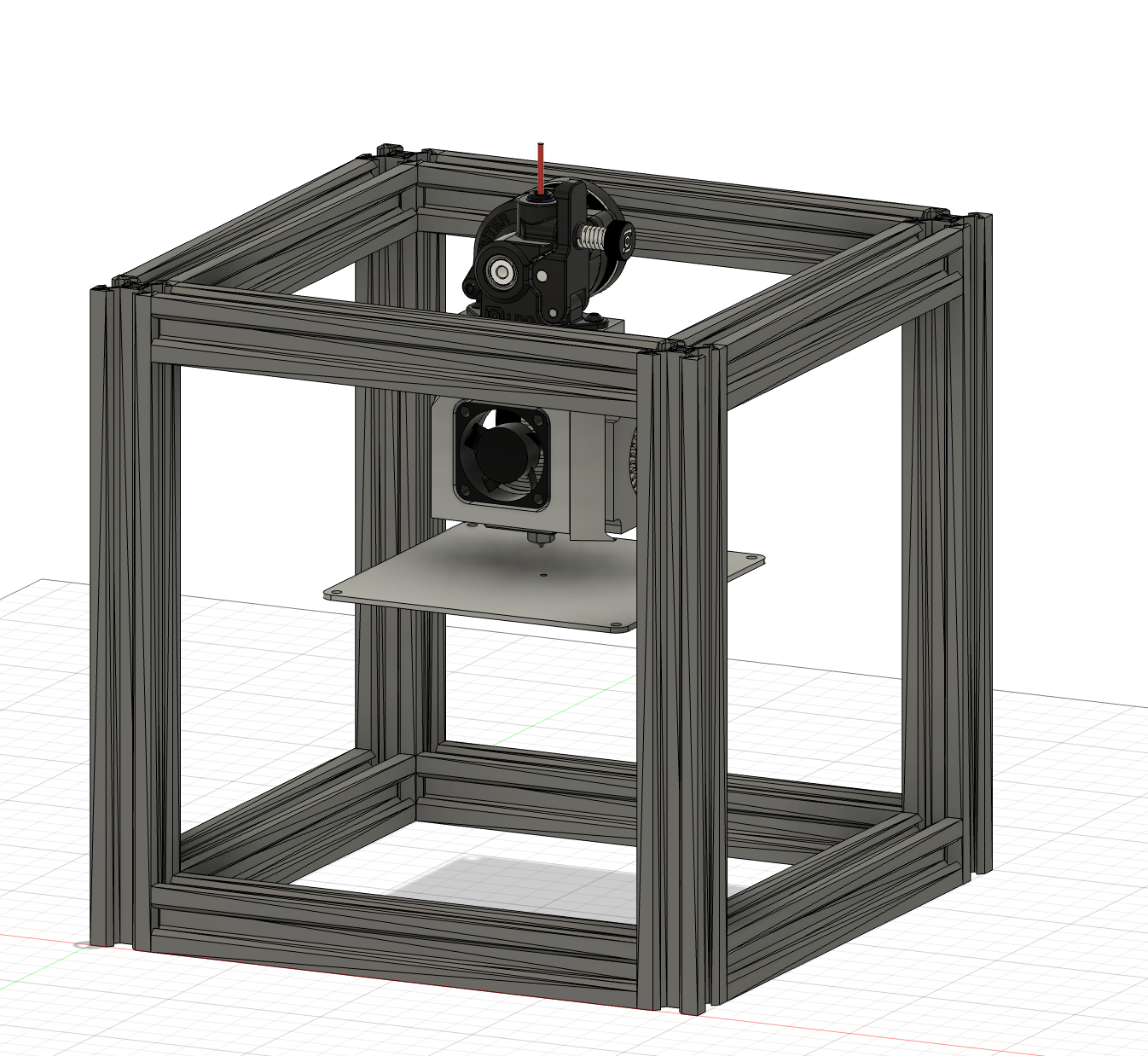
- Here is what it looks like in the full assembly so far.
CAD: +3 hours
+3 hours
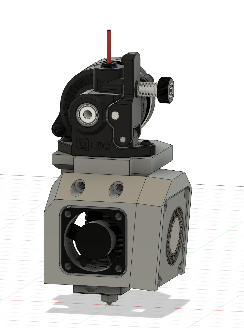
- I also changed the angle of the side fan to blow the air more towards the nozzle and to optimise space on the toolhead.
CAD: +1 hour
+1 hour
Time Spent on This Day: 5 hours
Research: 1 hour CAD: 4 hours
Day 4: March 11th 2025
Research CAD
- I did more research on toolheads and realised that I need to add a channel for the air to flow towards the nozzle. I researched different methods of this for my design.


- I then applied this to my CAD model trying not to impede on the parts that I already had. This proved much harder than I expected and I had many iterations of it before I finally achieved a result that I wanted.
Research: +30 mins CAD: +2 hours
+2 hours 30 mins
Time Spent on This Day: 2 hours 30 mins
Research: 30 mins CAD: 2 hours
Day 5: March 12th 2025
Research CAD
- I researched the different axes motion systems and what motors and linear rails to use. I think I will use MGN7 rails and MGN7-H for the carriage and I will use NEMA 14 Stepper Motors. I still don’t completely understand the belt system but I will model the rails and carriage connections first.
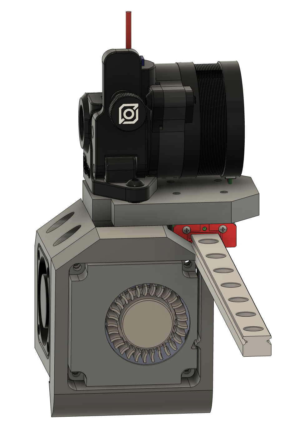
- I then added the linear rails to my full assembly and realised that it would be better to go with MGN9 rails and MGN9-H carriages so I added them instead. This meant I had to change the connection on the toolhead to fit on the MGN9-H carriage.
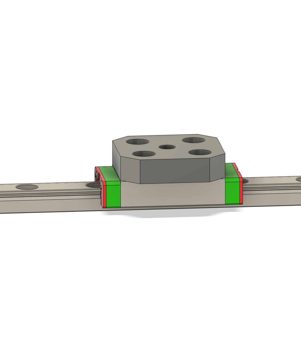
- I also had to model some connectors to connect the X-Axis linear rail to the Y-Axis rails so that they could move together. Here is what they look like.
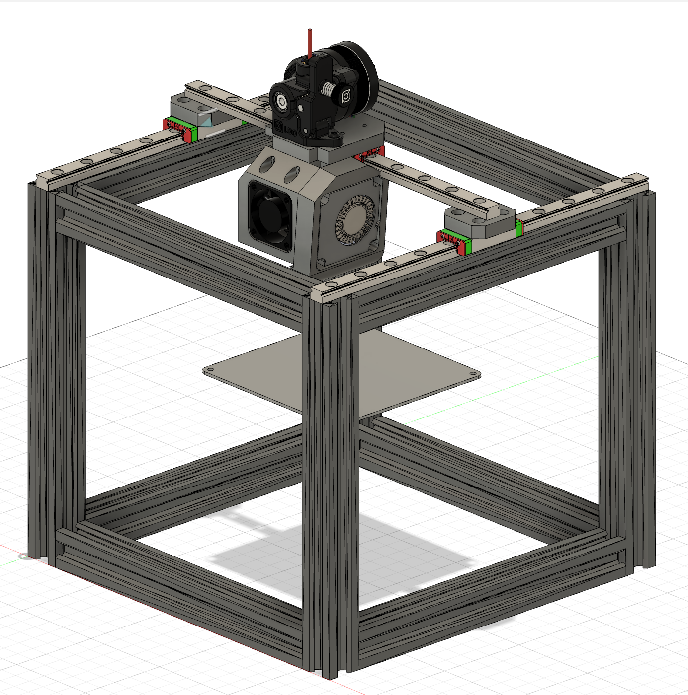
- I then put all the new and modified components together in the full assembly. Here’s what it looks like to far!
Research: +3 hours CAD: +3 hours
+6 hours
Time Spent on This Day: 6 hours
Research: 3 hours CAD: 3 hours
Day 6: March 13th 2025
Research CAD
- I did a lot of research on the X-Axis and Y-Axis motion systems and how to implement them, it was quite confusing how both the belts connect to the toolhead as I originally thought that one would connect to the toolhead, and one to the ends of the linear rail. I understand it now though after quite a bit of research.
Research: +1 hour
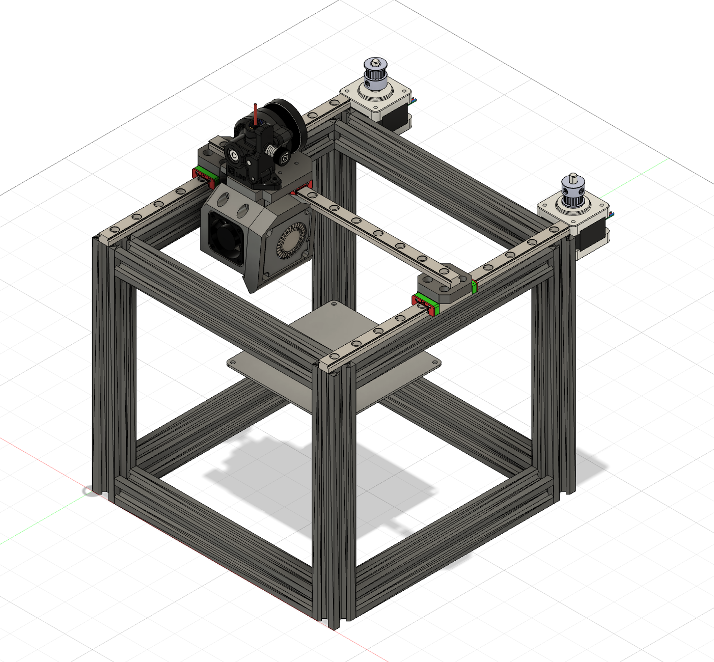
- I got started on the CAD for these motion systems, so far I added the NEMA 14 stepper motors and GT2 20 Teeth Pulleys. Here is what it looks like in the full assembly so far.
CAD: +1 hour
+2 hours
Time Spent on This Day: 2 hours
Research: 1 hour CAD: 1 hour
Day 7: March 24th 2025
Research CAD
-
I researched how to add the pulleys and belts to my system and espeecially how to connect them on the toolhead end.
-
I realised that it might be better to have the X-Axis linear rail with the carraige facing forwards rather than upwards. This would mean that I had to redesign my X-to-Y-Connectors for the linear rails.
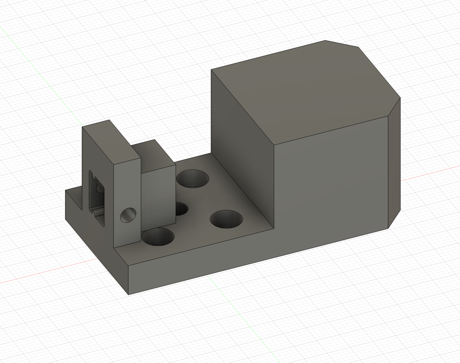
- It was difficult to design these without heavily limiting the range of motion of the carraige in the X-Axis so I had many iterations. Here is what the final design looks like. It screws onto the Y-Axis linear rail and the X-Axis rail slots into it and is secured with a srew.
Research: +30 mins CAD: +2 hours
+2 hours 30 mins
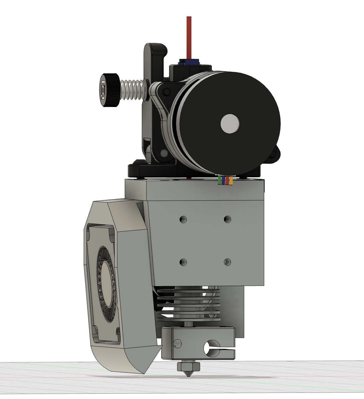
- I then also had to edit the toolhead so that it would work with this new sideways rail system. Heres what it turned out like.
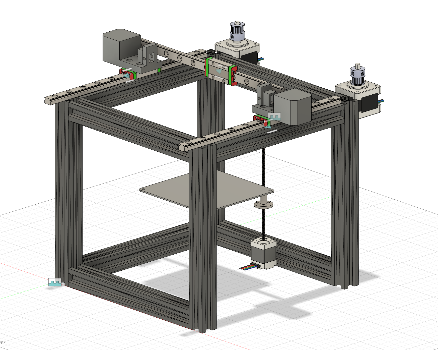
- This is what it would look like in the full assembly. I haven’t adjusted any dimensions of anything else so it doesn’t fit together properly yet.
CAD: +1 hour 30 mins
+1 hour 30 mins
Time Spent on This Day: 4 hours
Research: 30 mins CAD: 3 hours 30 mins
Day 8: March 28th 2025
CAD
- I realised that for the X-to-Y-Connector I need a different slot for the left side and the right side so that the linear rail can go all the way through.
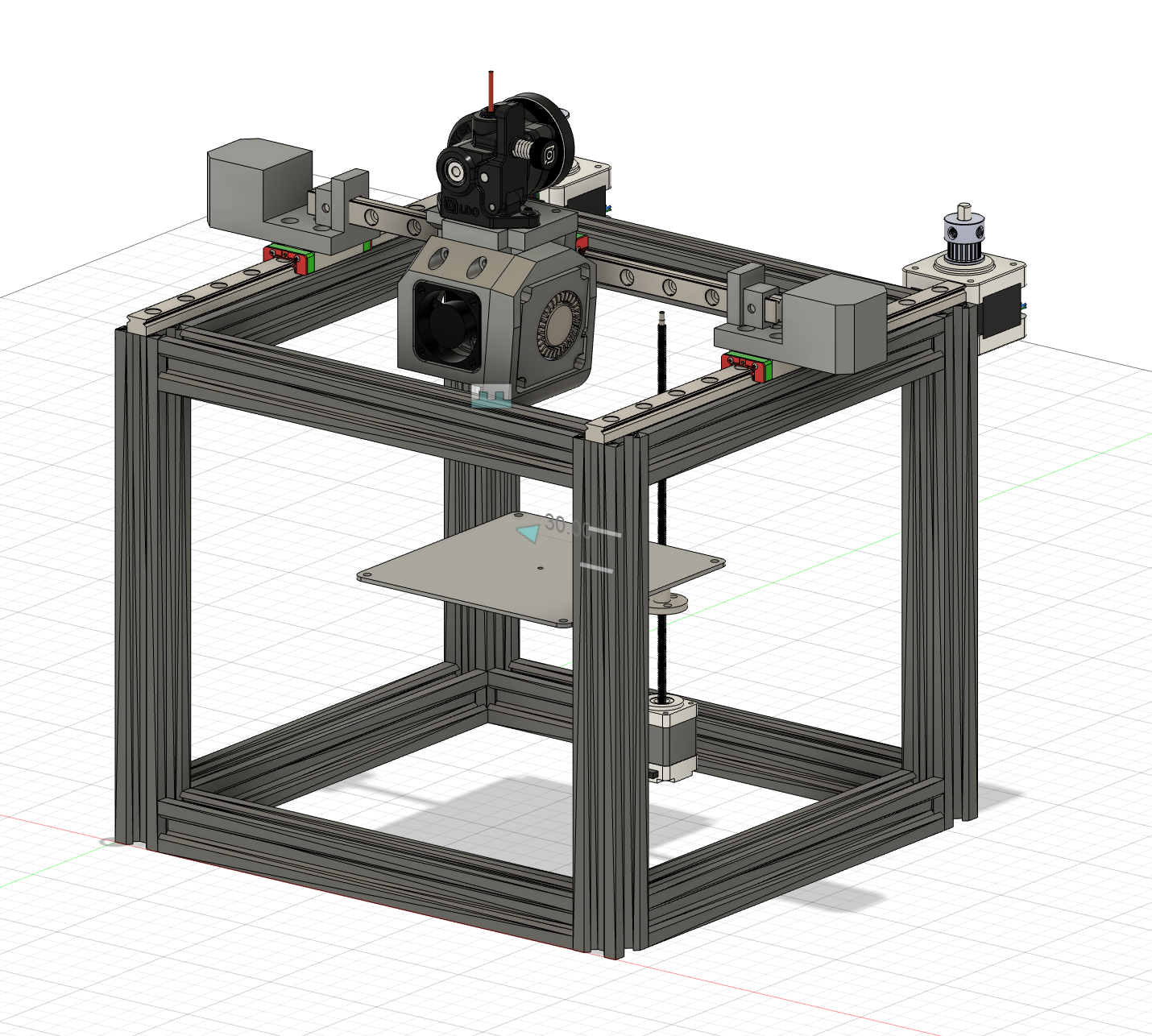
- I then had to adjust the dimensions of the aluminium extrusions in order to fit the new connectors and adjust the positions of all the other components for the full assembly. Here is what it looks like.
CAD: +3 hours
+3 hours
Time Spent on This Day: 3 hours
CAD: 3 hours
Day 9: March 29th 2025
Research CAD


-
I added mounts at the corresponding heights to the X-to-Y-Connectors for the pulleys to sit for the belts. Here’s what it originally looked like. I also added slots on the back of the Toolhead for the belts to feed through and here’s what that looked like.
-
I didn’t like how bulky the X-to-Y-Connectors turned out so I did some research on how other people cut down on the size while still maintaining the function.
CAD: +1 hour Research: +1 hour
+2 hours
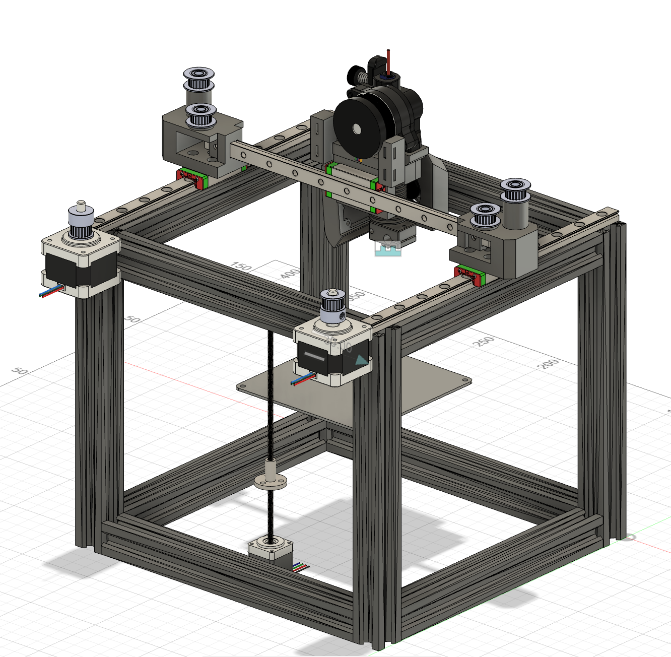
- I came up with this design to cut down on the size while still maintaining the same function as the other design. Here’s what it looks like in the full assembly.
CAD: +2 hours
- I still need to add a mount the the NEMA 14 Stepper Motors so that they are in the correct spots as well as adding pulleys on the front side of the printer for the belt. I think I will come back to this later.
+2 hours
Time Spent on This Day: 4 hours
Research: 1 hour CAD: 3 hours
Day 10: March 30th 2025
Research CAD
- I did some research on all the parts of the printbed. I had already chosen the heatbed and to have a magnetic PEI Plate. I decided on putting a 3mm Silicone Sheet under the heatbed as an insulator to separate the heat from the 3D printed base. I am using a NEMA 17 Stepper Motor with Intergrated Lead Screw as well as 2 8mm Linear Rods for support to control the Z-Axis movement of the bed.


- I designed the printbed around these things and here’s what the finished bed assembly looks like by itself and with the motor, lead screw, and rods.
Research: +1 hour CAD: +2 hours
+3 hours
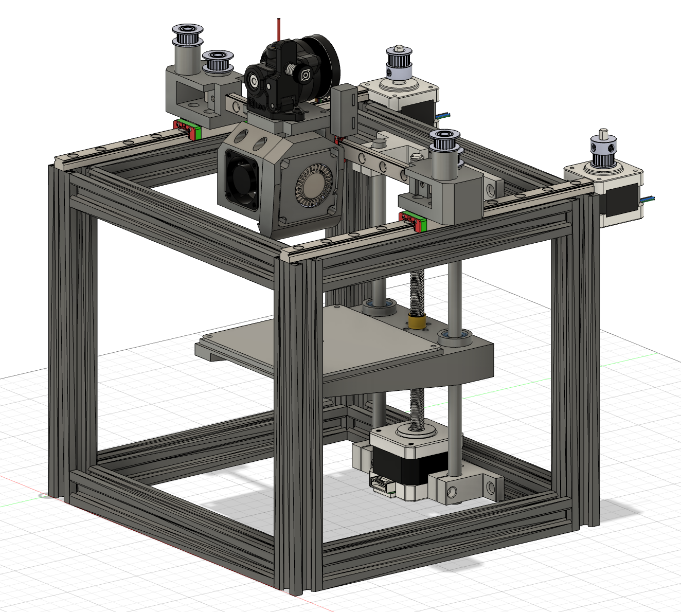
- Here is what the full assembly looks like so far. I think all I have left to do is to finish it is the X and Y Axis pulley and belt system and to add the endstops that I made at the start. Although I’ll probably think of something else left to do later :pensive:.
Time Spent on This Day: 3 hours
Research: 1 hour CAD: 2 hours
Day 11: April 1st 2025
CAD BOM
-
I worked on making the end pulley holders for the XY-Belt system. The reason they stick out on the side is because I have to leave enough inside space for the toolhead to reach every corner of 100mm2.
-
I am going to secure the pulleys with a long screw going from the top into a heatset insert at the bottom. They are going to be separated by a platform.
-
CAD: +1 hour


-
Here is what they look like by themselves and in the full assembly.
-
I then worked on adding all the parts I have so far into my Bill Of Materials with links to where I will source them from and prices.
BOM: +1 hours
+2 hours
Time Spent on This Day: 2 hours
CAD: 1 hour BOM: 1 hours
Day 12: April 2nd 2025
CAD
- I created a holder/mount for the motor that sits on the right side of the frame (when looking from the front).


- I tried to add support to it from the diagonal to make sure that it would be strong enough to hold the weight of the motor. Here is what it looks like by itself and in the full assembly.
CAD: +2 hours
+2 hours
Time Spent on This Day: 2 hours
CAD: 2 hours
Day 13: April 5th 2025
CAD
-
I first modelled the mount for the screen that I am using, the BIGTREETECH MINI 12864 V2.0 LCD Display Screen. This was difficult, as I had to figure out what to do to secure it.
-
I also modelled corner brackets to connect the Aluminium Extrusions together.
-
I changed the height of the of the pulleys so that they are both at the lowest possible height. This does a few things:
- Cuts down on filament used
- Puts less stress on the motor holder as it will have a centre of gravity closer to the bracket
- Makes the overall design smaller to fit into the size constraints that I have (250mm3)
-
My Fusion finally decides to allow me to change the appearances of objects and components so I changed the colours of everything to what they will finally be.
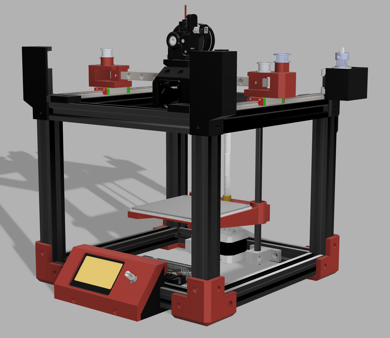
- Here is what my first render looks like… I’m so excited it looks so cool and it’s all coming together :grin:
CAD: +4 hours
+4 hours
Time Spent on This Day: 4 hours
CAD: 4 hours
Day 14: April 6th 2025
CAD
- I remodelled the motor mount and the end pulley holders so that they will fit into the the design for the corner mounts. They now correspond to the corner mounts to make it easier and more consistent.
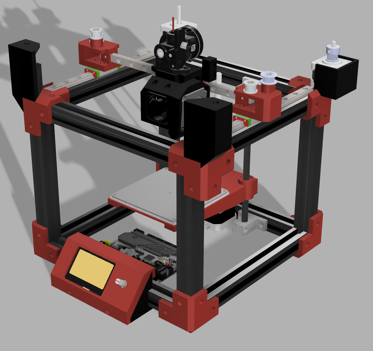
- Here is another render (yay!)
CAD: +3 hours
+3 hours
Time Spent on This Day: 3 hours
CAD: 3 hours
Day 15: April 9th 2025
Research CAD
-
I modelled the second motor mount and also mounted the Z-Axis Endstop.
-
I mounted the Z-Axis Endstop to the bottom of the top frame at the back. This is so that when the bed rises to the Layer 0 height, it will stop just before hitting the nozzle. I experimented with having the Endstop mounted to Bed Assembly itself but due to size constraints, realised that this wouldn’t work.


- Here’s what that looks like as well as the full assembly.
CAD: +3 hours
+3 hours
- I also did some research on Power Supplies. I calculated the full power draw and have settled on a 24V 350W Power Supply. I will also use a Plug and Switch Module so that I can plug in the wire that will connect to the wall and have the safety of being able to turn it on and off from the printer.
Research: +2 hours
+2 hours
-
What I now have left to do is mounting the Power Supply and Plug and Switch Module to the printer as well as the Mainboard. I also need to mount a Raspberry Pi, so that I can run Klipper and have remote printing.
-
I’m so close!!!
:grin: :grin:
Time Spent on This Day: 5 hours
Research: 2 hours CAD: 3 hours
Day 16: April 10th 2025
BOM
-
I updated my Bill of Materials with any relevant parts that I had not yet added. I realised for a few of the parts I had linked that they were ‘Max. 1 pcs/shopper’ but I needed multiple of the part, so I had to find new sellers that allowed me to get more than 1.
-
I realised this is a much bigger problem than I thought, and I need to update more parts than I anticipated. I’ll fix it later though.
BOM: +1 hour
+ 1 hour
- Also, Fusion stopped opening my files on my laptop so I’ll have to fix that :confounded:
Time Spent on This Day: 1 hour
BOM: 1 hour
Day 17: April 15th 2025
Orders BOM
- I ordered my first part from AliExpress which is the LCD Screen. This is the item I decided to use the Welcome Deal for so I got it for $10.55AUD.
Orders: +1 hour
- I then went through the Bill of Materials some more to make sure all the parts I had there well within price range, and had reasonable shipping times and fees.
BOM: +2 hours
+ 3 hours
Time Spent on This Day: 3 hours
Orders: 1 hour BOM: 2 hours
Day 18: April 17th 2025
Orders
-
I ordered another 15 parts which was almost all of the other parts I need. They are set to be delivered somewhere between the 20th and 30th of April.
-
I wasn’t able to order the Hotend because for some reason the payment kept failing; I think AliExpress had flagged the card as suspicious for no reason. I tried to submit an appeal for the payment but it wouldn’t allow me to. So I tried to chat with customer support but I was stuck going round in circles with the bad AI ‘customer support worker’ that kept suggesting the same solutions that had already not worked :roll_eyes:
-
I also ordered my Power Supply from a local eBay seller which was cheaper and easier.
Orders: +3 hours
-
I also realised after ordering one of the parts, that the seller was very suspicious so the order may not get fulfilled. Hopefully I can get a refund.
-
So now I guess it’s just a case of waiting :hourglass_flowing_sand: :alarm_clock:
+ 3 hours
Time Spent on This Day: 3 hours
Orders: 3 hours
Day 19: April 18th 2025
Orders
-
I continued to try to pay for the Hotend; I tried many different sellers but all of them failed. Eventually I ended up having to use a different card to pay for it and it worked first time.
-
No idea why it was so difficult but it was pretty annoying. At least I got it ordered in the end. :neutral_face:
Orders: +1 hour
+ 1 hour
Time Spent on This Day: 1 hour
Orders: 1 hour
Day 20: April 23th 2025
Orders Assembly
-
My first item arrived today :partying_face: which was the LCD Screen
-
I put the mount for it on to print, so that when the other parts arrive, I can mount it to the Aluminium Extrusions
Assembly: +30 mins
+ 30 mins
Time Spent on This Day: 30 mins
Assembly: 30 mins
Day 21: April 25th 2025
Orders Assembly
-
A bunch of parts arrived today! :tada::tada: Here is what arrived:
-
GT2 Timing Pulleys
-
Orbiter v2.0 Extruder
-
3010 Axial Fan
-
4010 Blower Fan
-
Power Switch and Socket*
-
GT2 Timing Belt
-
PC3 M6 Connector
-
M3 Heatset Inserts
-
Magnetic PEI Plate
-
GT2 20 Tooth Pulley
-
GT2 No Tooth Pulley
-
Silicone Foam Mat
-
M3 Bolt and Nut Set
-
2020 200mm Aluminium Extrusions
-
MGN9H Linear Rails
-
Power Supply (from eBay)
-
-
*When I ordered the Power Switch and Socket, I accidentally ordered it without the wires. It’s actually cheaper and easier for me to just buy it again but with the wires rather than buying the wires and crimping tools, so that’s I’ll do.
-
The Power Supply is larger than I expected so I will have to redesign the holder/mount for it.
-
I set the Corner Brackets to print so that I can assemble the Aluminium Extrusions.
Assembly: +30 mins
+ 30 mins
Time Spent on This Day: 30 mins
Assembly: 30 mins