3d Spire
3dspire
Idea: Simple CoreXY printer (maybe move over to non-planear printing)
In the budget, I have three motors available for z with lead screws. With the bed able to pivot, we can create a plane with the bed as 3 points define a plane. With this and custom slicing, this allows for non-planer printing.
Goal:
- Fast and accurate parts
- Relatively space-efficient
- Option to add an enclosed (I have a sheet of plexiglass but no accurate way to cut/drill)
Features:
- Higher torque motor compared to COTS printers for the same size
- Modular hotend, hotend mounts on with two screws, and using canbus allows for quick disconnections.
Parts list: https://docs.google.com/spreadsheets/d/1-p1FSMkBJRRGZg3B695Q9pYF5o_9TisIYr6g5MQPlGU/edit?usp=sharing Cad link: https://cad.onshape.com/documents/ecbd1ecc80a05f878c9e2e54/w/9dcd75629b77e3e1a0cdb3f1/e/acfe18e92d99a71a0dff7b85?renderMode=0&uiState=679ed00ee3c0cc435fb095f1
Update one:
Time spent: 4 hours
I created an initial parts list. Chose a BTT motherboard due to the low price and having four motor outputs. I need four due to having two z motors. I am using Nema 17 42x48 due to the high torque and low price. The pack has five motors, which I might want to use to add a triple z system for nonplanar printing.
Update two
Time spent: 2.5 hours
I started to cad out with a basic design with linear rails and extrusions for the motion system. Used 3D printed joints for low cost and flexibility of design. Added a COTS hot-end assembly for simplicity. I will change this later.
Update three
Time spent: 4 hours
I changed the rail from mounted on its side to mounted on the top of the extrusion. This helps me make the whole printer smaller.
I also changed the hotend+extruder temp to a dragon bunner. I will probably use this mounting system to allow esay swap of hotends. I also changed the size to a 250x250 build plate after realizing how small a 180-180 is.
Update Four
Time Spent: 5 hours
I figured out the belt paths from this image:
From that, I designed the v0 part of the belt systems. I added double sheer support on the motors to prevent unnecessary wear and tear.
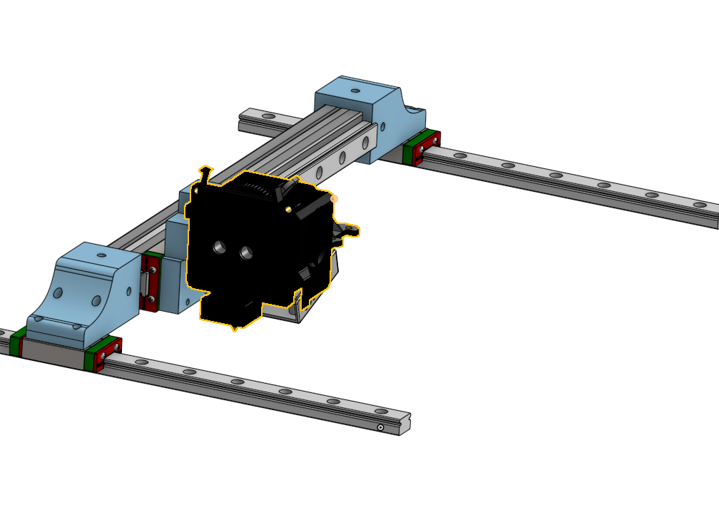
Update five
Time Spent 20 hours
I designed the z and bed mounts. This required me to move the crossbeam holder up to have the z-axis mounts on the inside, as shown below. I wanted this so I could easily bold on side panels later without worrying about producing elements. I chose to 3dpint an extrusion due to extrusions being sold in packs of 2 or 4, this saves around 10-15 dollars and should not compromise on anything.
Update six
Time spent 10 hours
For my hot-end assembly, I wanted to use 2 5015 fans for a lot of cooling; this makes the whole size pretty big. Along with this, I would need a good extruder and hot end to keep up. I chose to use an x1 hot-end clone due to the low price and pretty good performance. I also used a COTS extruder due to this design being around the same price as the motor and gears needed. I also added a BL touch for bed leveling.
Update seven
Time spent 1 hour
I used some physics to calculate the maximum acceleration of the x-axis with one motor running.
The theoretical max acceleration that the motor can handle in a perfect world is around 73k. This will NOT be the real world due to friction and resonance of the frame being the primary constraint in speed. I talked with my physics teacher, and he suggested building it and test, but the calculations for it would be extremely hard to do, if not impossible, due to this being a complex shape. Because of this, I could not find the frame’s resonance frequencies. For rigidity, I designed the frame to have deep pockets with overlap between 3d printed corner pieces and the aluminum extrusion.
I also tested different materials for the side pieces by printing out test corner pieces and seeing the force for them to break. (I can’t find the paper where I recorded data, but soon!) Setup:
I realized after the fact that due to printing the pieces flat to save on filament, I was actually just testing the layer strength of each print, not how strong they were.
Update eight
Time spent 4 hours
Designed a smart filament sensor; I have two sensors to detect filament, a basic limit switch to detect the presence, and an optical encoder to see if the filament moves.
Cad img:
PCB: https://github.com/JeffreyWangDev/infill-pcb