David
Made by: @Raygen Rupe // lordbagel42 Repository link: https://github.com/lordbagel42/david Total hours so far: 50
- I have a 3D printer or will be getting one before March 21st
DAVID
DAVID: Da Awesome Very Interesting Device.
so how did I get here? what is this thing?
It’s a colinear tripteron. Or a delta tripteron. Deltaron. It’s a very unique printer, to say the least.
Scrolling youtube shorts looking at parallel kinematic robots, as one does, I stumbled across this beautiful video.
No idea who created it. Just a video with no likes, 6 views, and an account with just randomly generated letters as a name.
I felt I had to create it.
the master sketch
Master Sketching is a TDD design technique for making complicated assemblies and parts. OnShape could implement it a little bit better, but overall it’s done well. I normally just let my variable studio be my master sketch, but that breaks down as you might expect it would. For this project however, I felt it fit the technique perfectly for just trying it out. I’ll be honest, this journal is written 3 hours after I started designing things, so the sketch has gotten a bit..involved.
I give you: The Master Sketch.
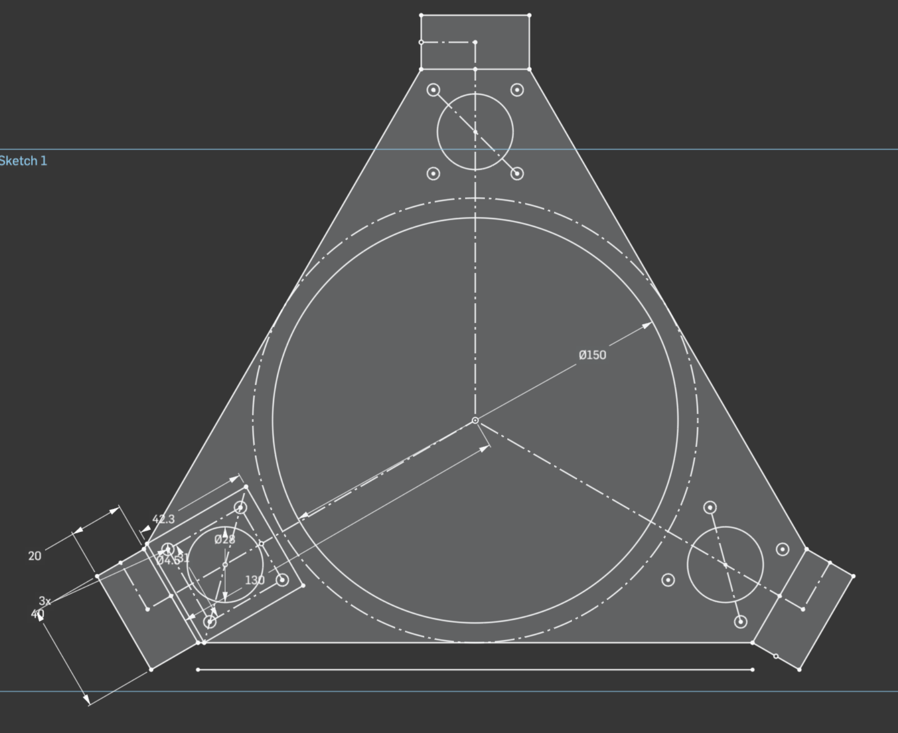
This one sketch shows the mounting for all 3 steppers, the bed, and all 3 of the vertical things I can’t remember the name of. And even includes the sketch line for the rest of the frame.
Honestly, it was pretty fast to make this thing. Took maybe half an hour in total over the last 3 hours? Overall, it’s worked well and I’ll be using this sorta master sketch system again. Just being able to derive this one sketch over and over has made life really easy. I’ve done similar things, but never really though to just genuinely put it all in one sketch. Harder to do for a CNC mill, I guess. Or modular things.
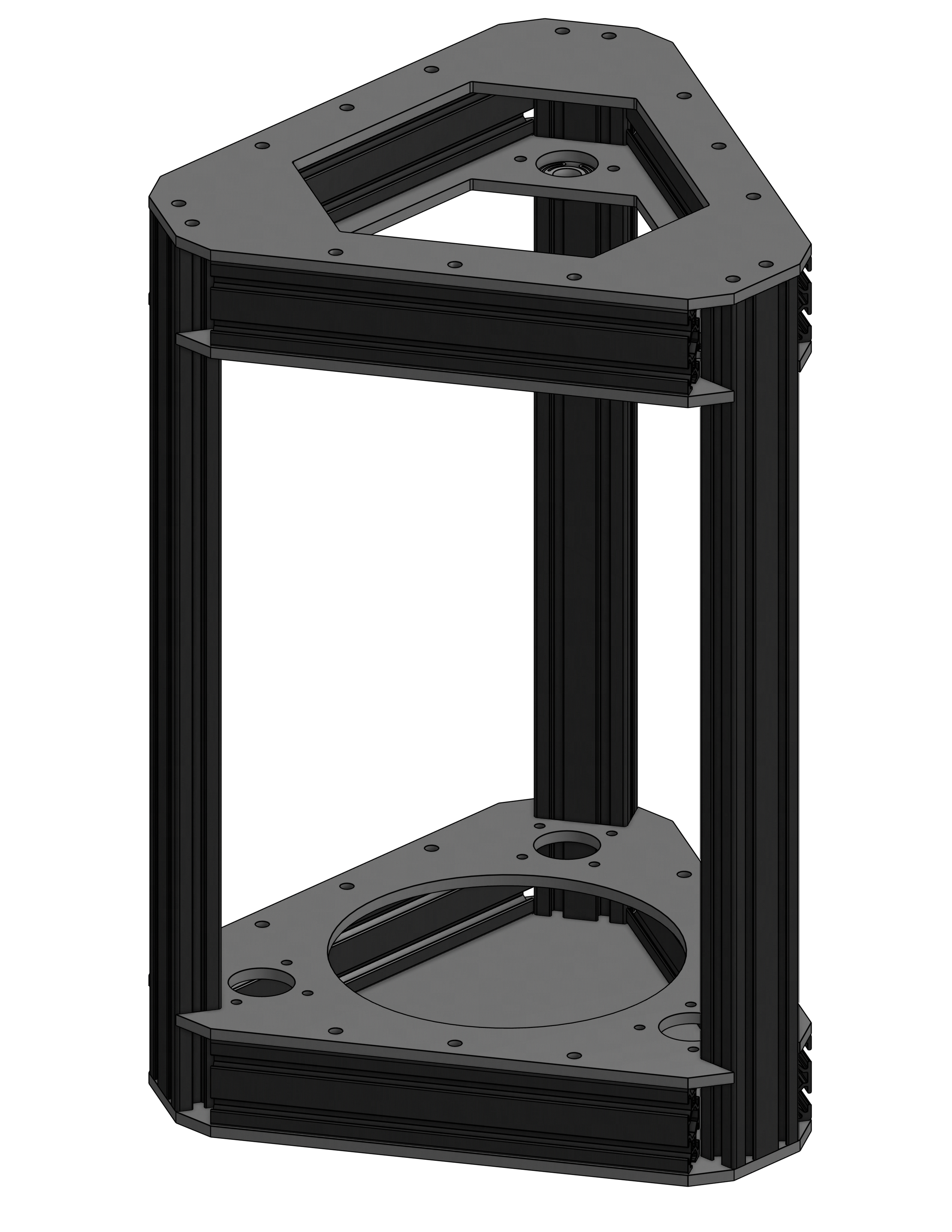
Here’s the frame design I’ve come up with:
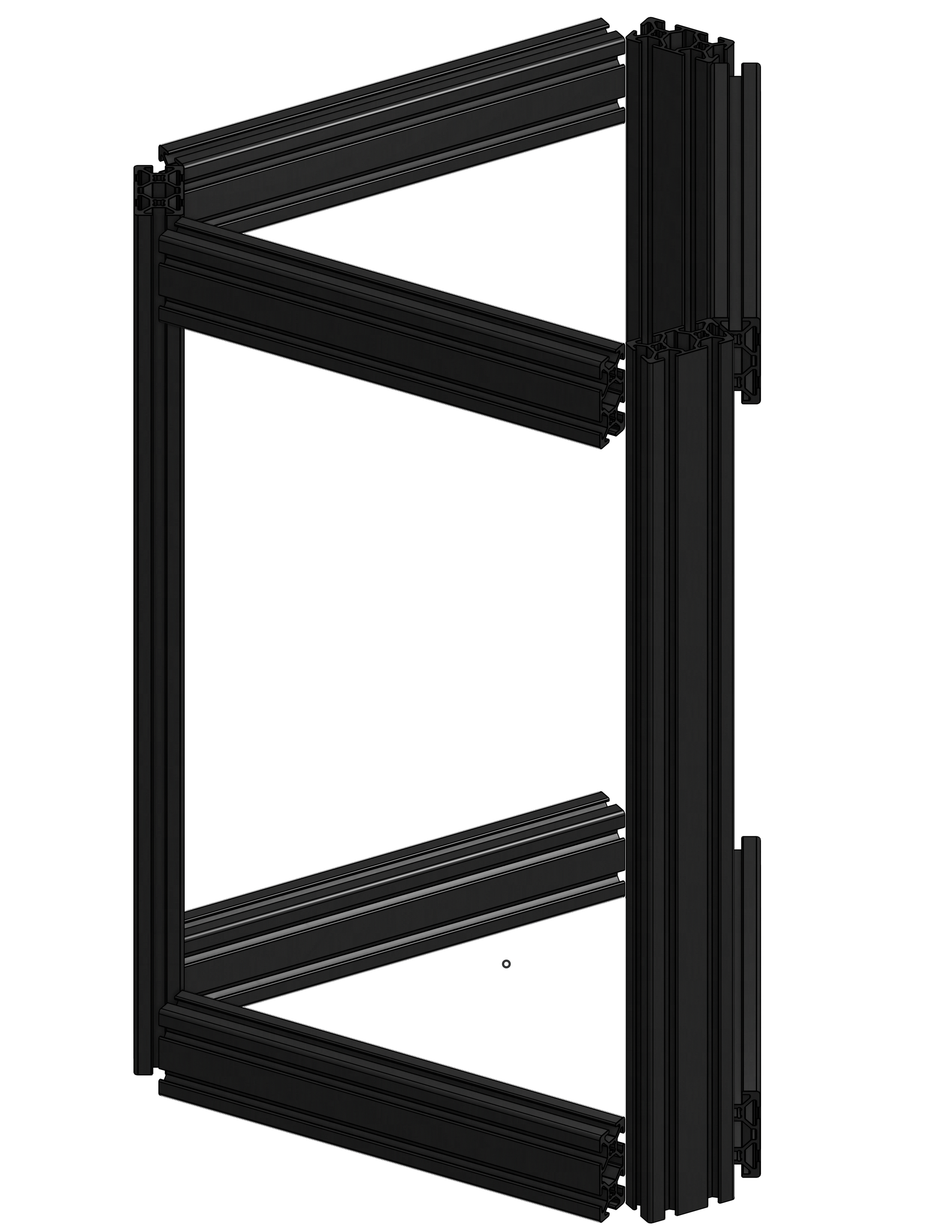
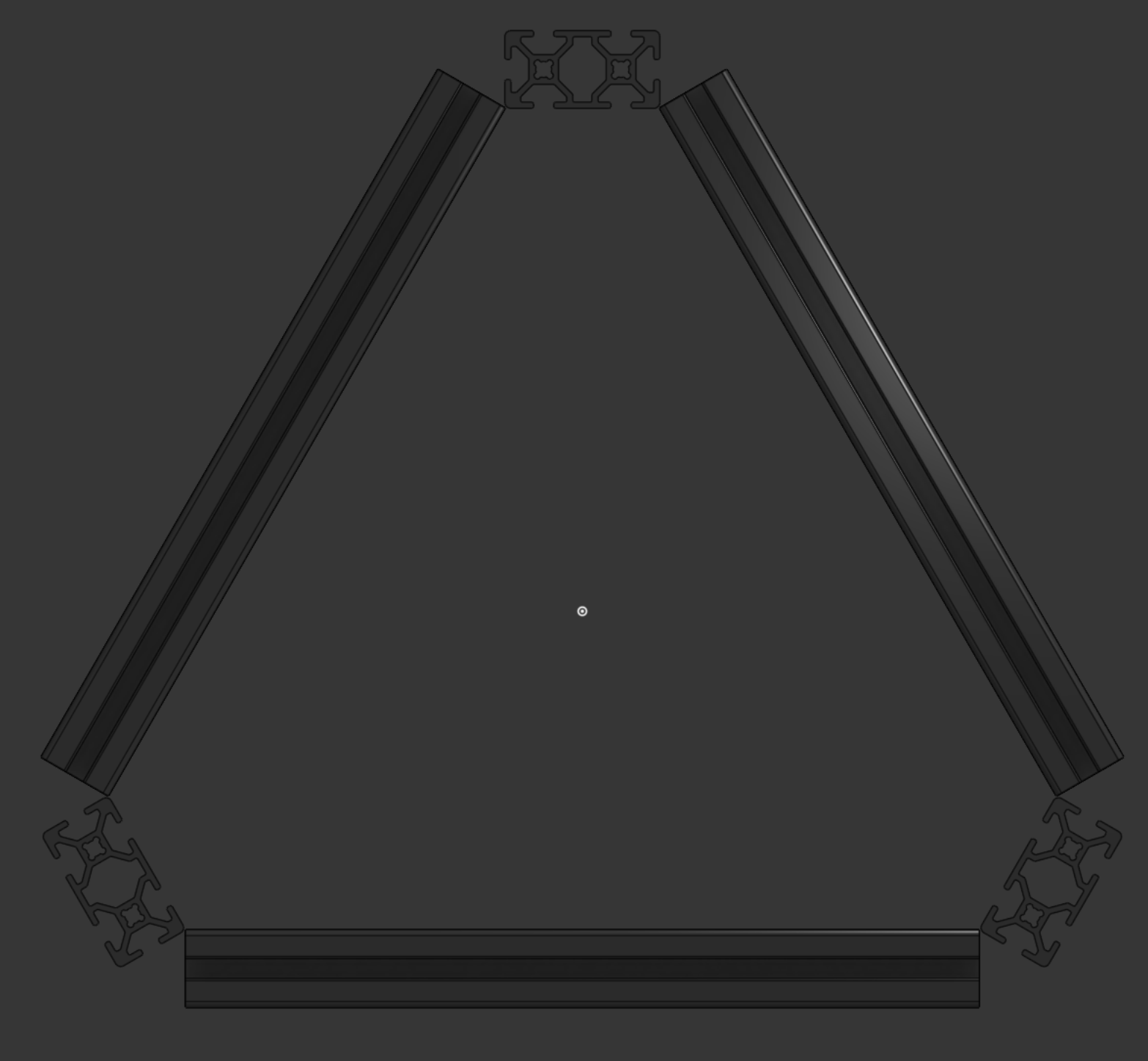
Nice and simple. Same as every other delta in existence.
…and then I got a little quirky with it.
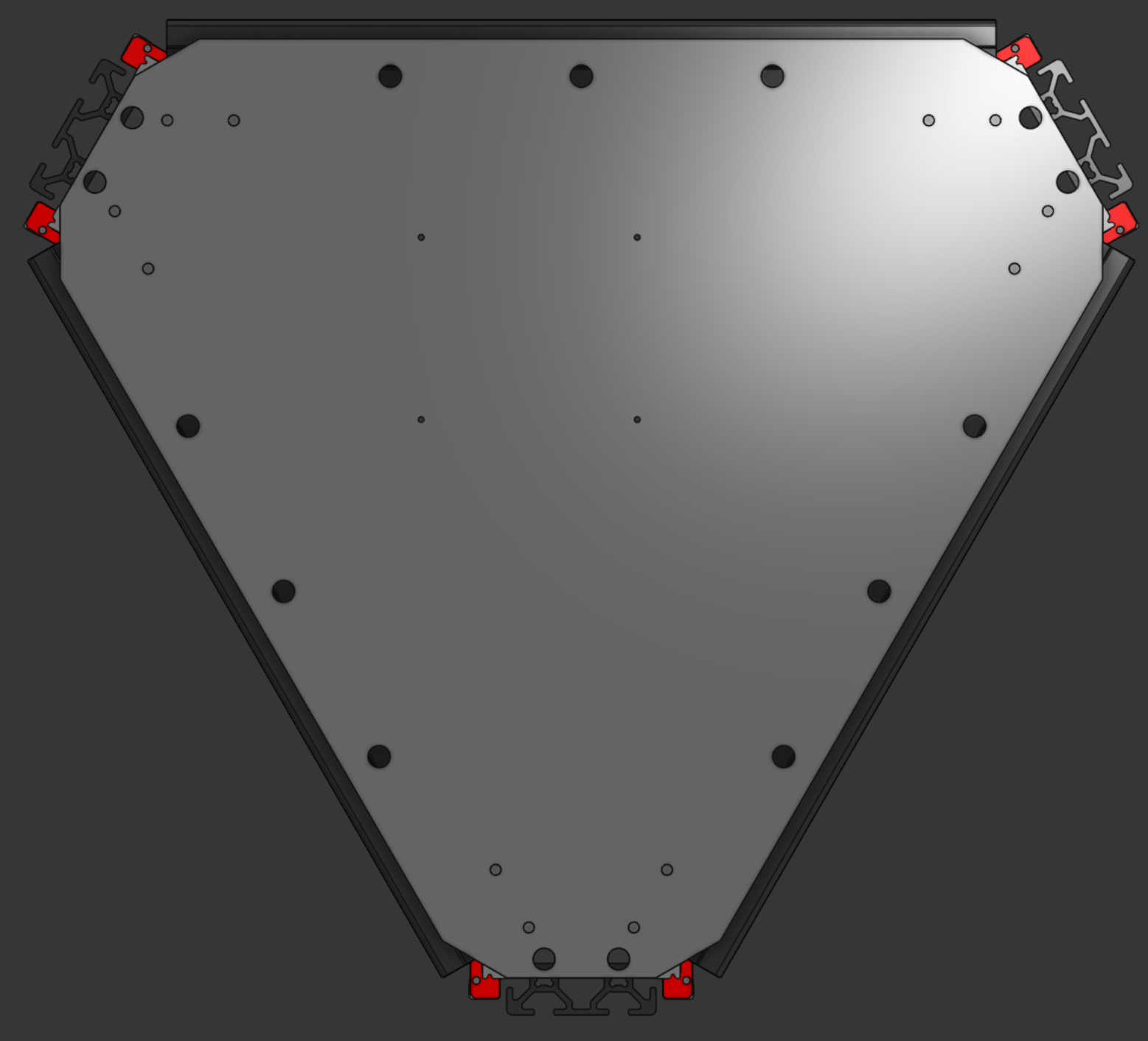
and I made this thing.
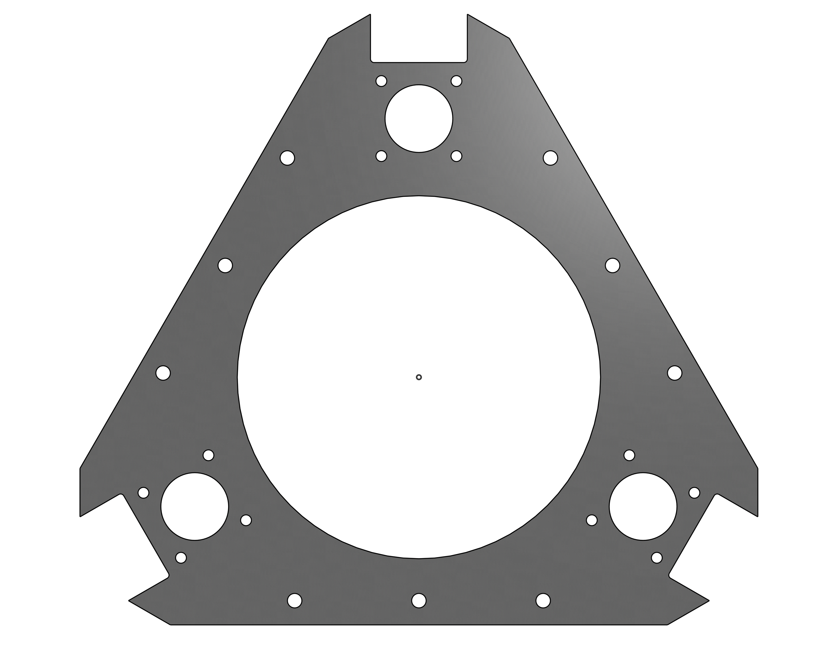
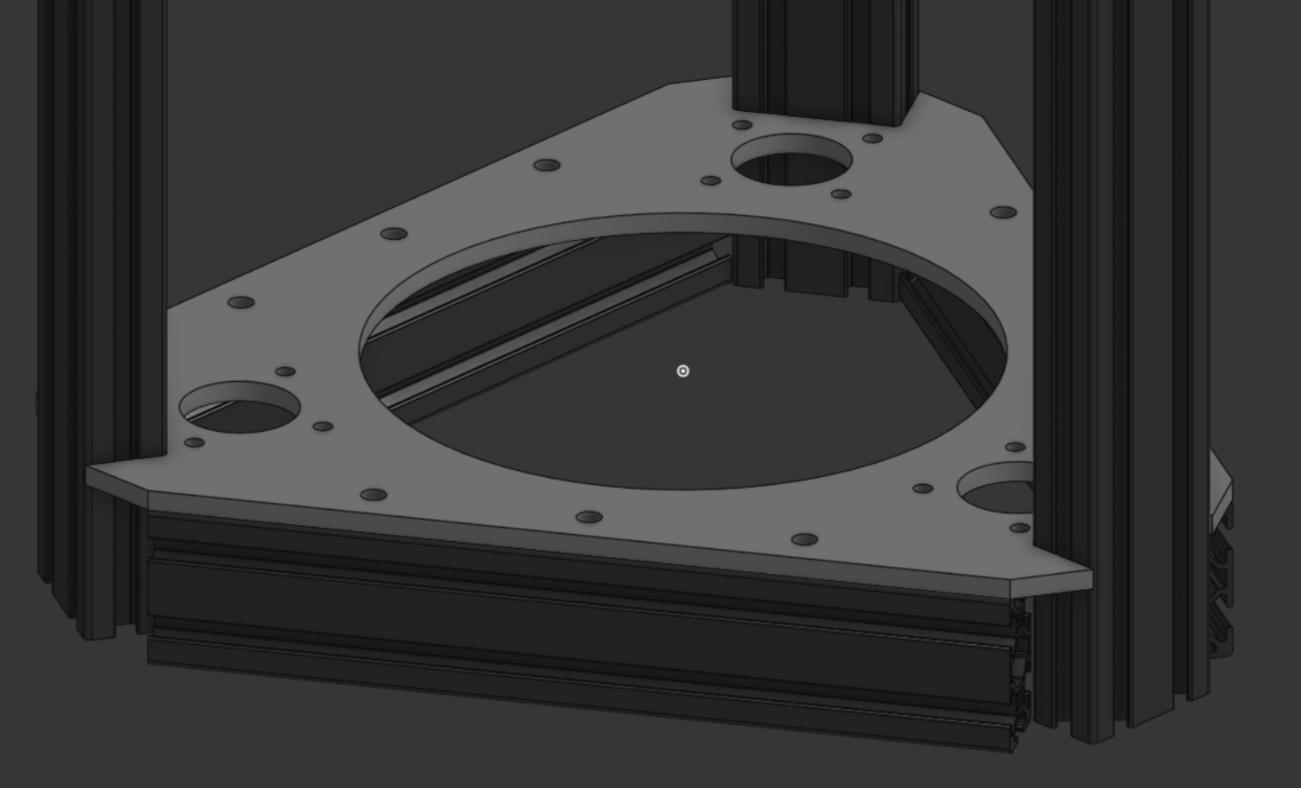
I figured, since I’ll need mounting holes anyway, why not just make a flat piece that mounts to the extrusions? And then I didn’t want things to be cantilevered, so…it ended up being this. This will likely be lasercut out of acrylic since that’s cheap, but it’s designed for aluminum. If I have the funds & time, I’m going to try and get it made out of aluminum.
One plate isn’t that expensive. It’s only about $12 to machine and then another $11 for shipping. Cheap as chips. Could even buy sheet alu locally and machine it on my schools CNC if I’m really careful about it. …but four plates is a bit more expensive than one.
I like aluminum, ok? Don’t judge me. This behemoth is as rigid as a house. Maybe more.
There is a large hole on the top. Currently, I have no idea where the cables and such will need to go. Solution: Big hole. I would like to change it to just being 2 holes, one for a PTFE tube and one for the toolhead board cable. God I love toolhead boards.
the most tedious sketch of my life
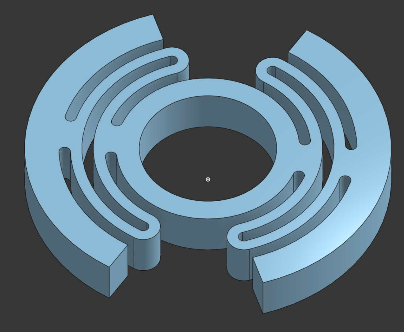
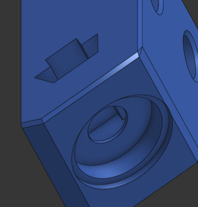
This is a bearing holder. I saw the idea once a long while ago. Essentially, you can’t put a bearing on the end of a leadscrew. That will cause the leadscrew to bind, as they’re kinda badly made and are not straight. They have to be able to flex.
Holding the top looks nice, though. So you get this thing.
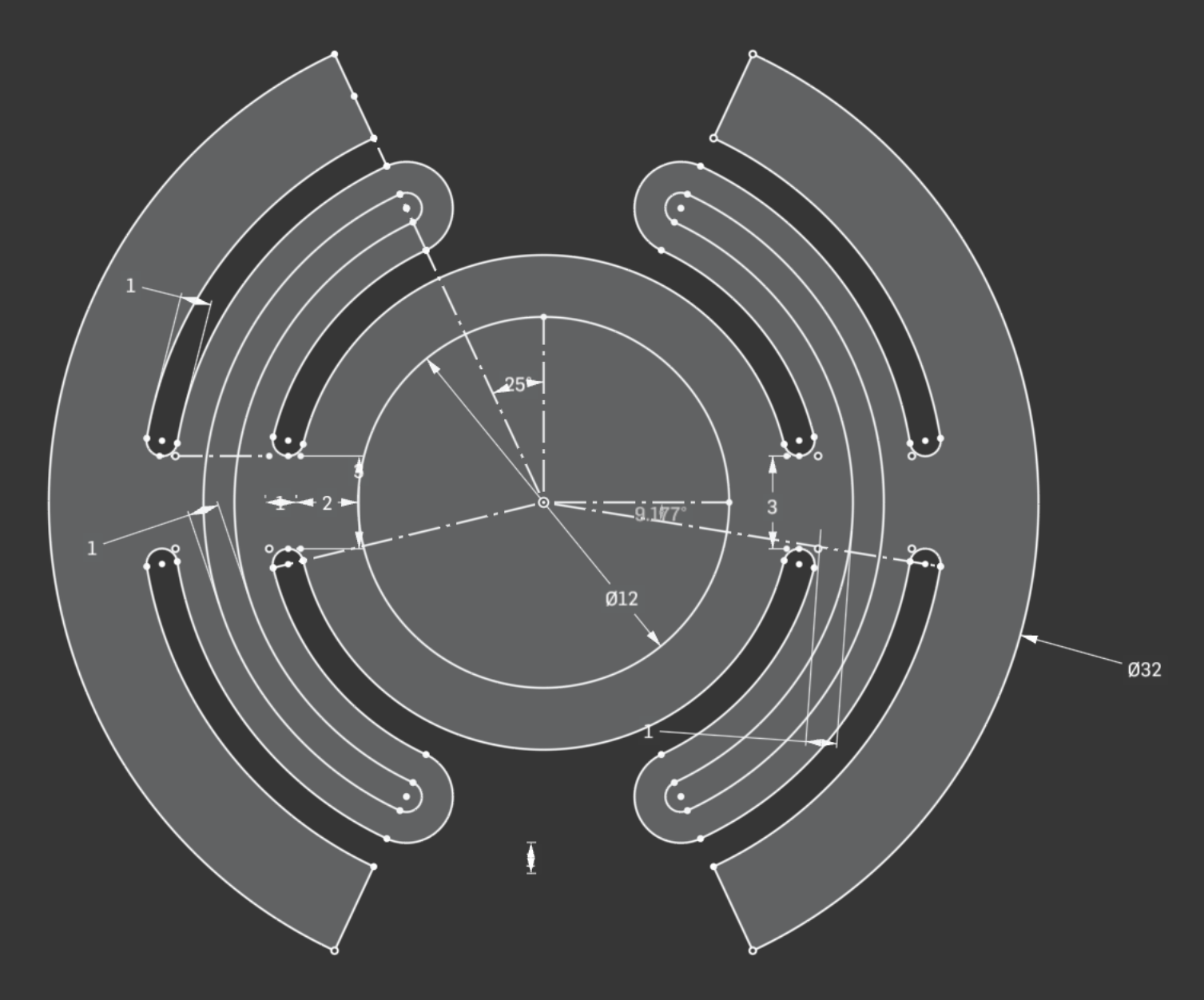
This took me an hour to make. Maybe hour and a half. I restarted 5+ times. It doesn’t look complicated, but model this thing yourself and you’ll see why it sucked. It’s just a compliant mount for a bearing on the top of the leadscrews. That’s all it is, lol.
Anyway. That’s all I’ve done for now. Going to start working on the tripteron arms themselves. Ideally I would use carbon fiber tubes for the weight savings, but my brother has yet to finish his filament winder so I’ll have to take that idea out of rotation. Perhaps I make wooden arms on the lathe though—lightweight and decently strong. Plus, it could look cool. Probably just going to end up printed though, lol.
Overall time: 3.5 hours.
turns out you aren’t supposed to use leadscrews on a delta.
I just spent half an hour trying out a couple different leadscrew mounts…
Oh well. I’ll nuke it all and switch to belts I guess. Oops.
this is cursed in the best way
Since I have an aluminum sheet for the base, I can just tap that and bolt things into it. It makes mounting things very easy. …so I crafted up this.
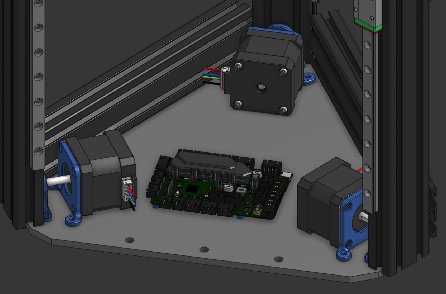
Yes. That is a SKR Pico with 3000 parts. The render for this thing is going to be beautiful.
Here’s the motor mount stuff itself:
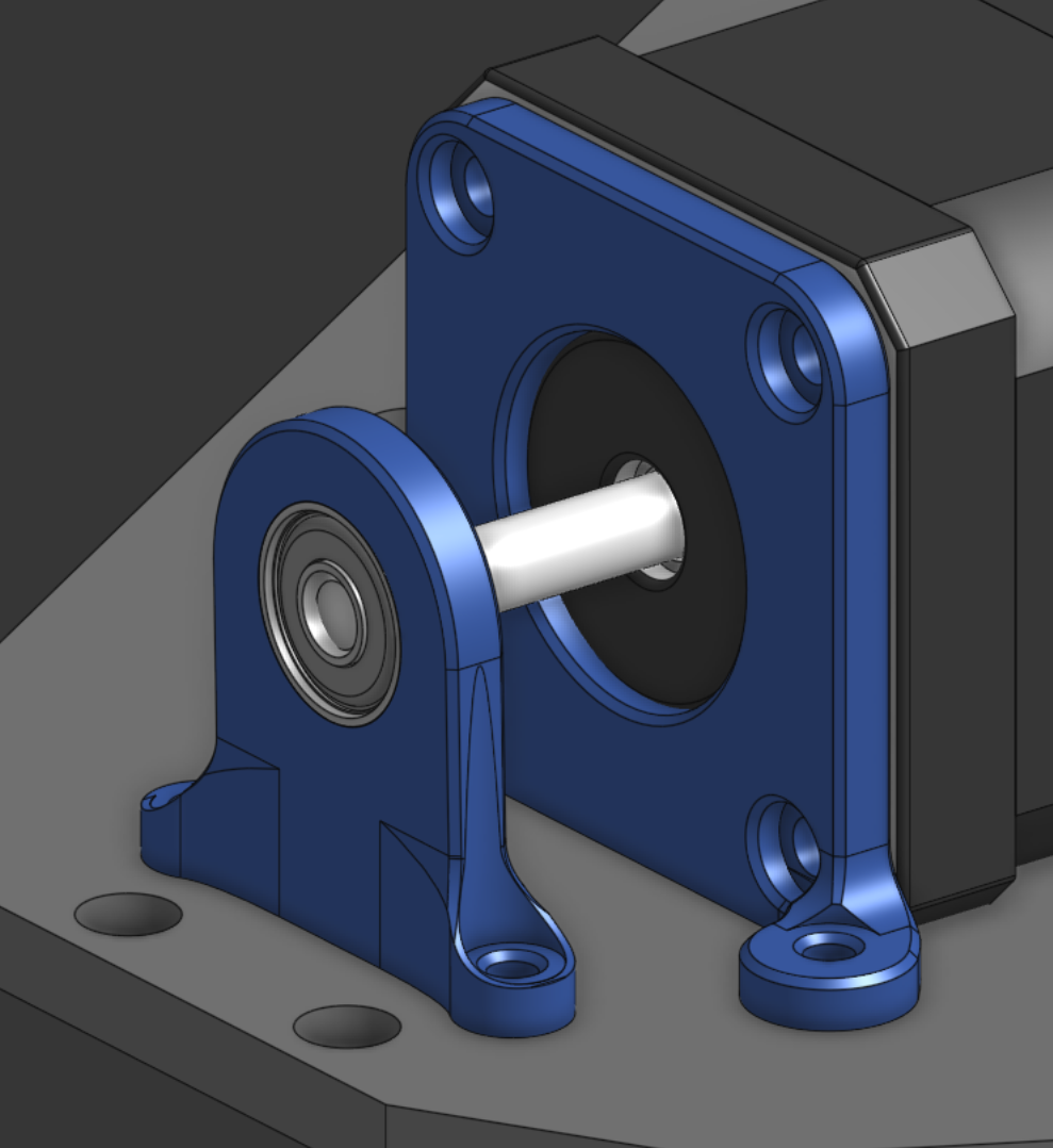
I’ll put the screws in later. I need to stop using screw holes in my sketches, the Onshape hole function is kinda wonderful. But then your sketches don’t tell you as much info. Maybe I just start using construction holes, lol.
I have no idea how strong this mount will be. I’ll test it out when my screws I ordered for a different project arrived, though. I think it’ll be strong enough.
The amount of holes in this one plate is getting a little insane.
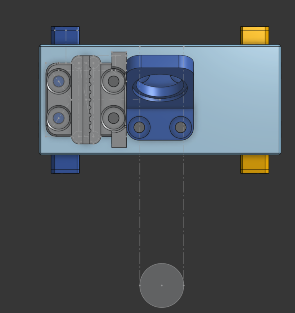
tunnel vision will be the death of me
Look at this lovely, beatiful belt clip. It’s great.
Note how there is nowhere for the arms to mount on this thing.
I entirely forgot the point of this structure is to hold onto the arms. That’s an extra few hours I won’t get back. Lol.
I’m going to just kinda cheat and call it good.
i’ve messed up horribly. like so badly.
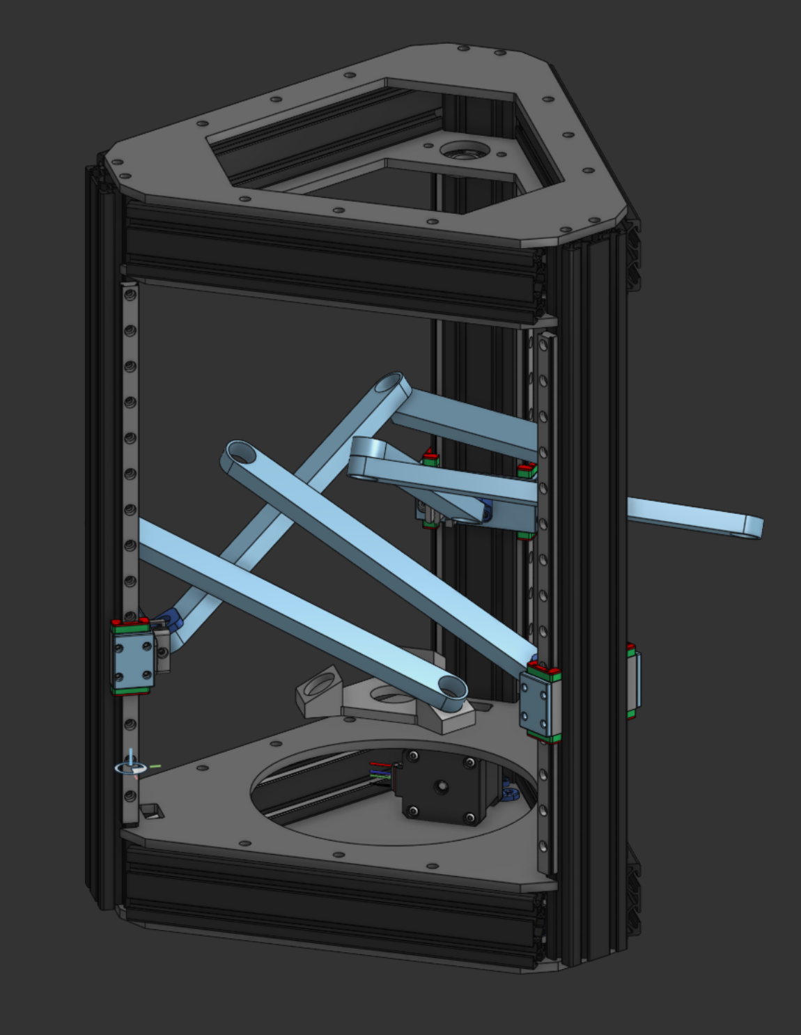
That’s the device currently. I managed to miss a, perhaps key, part of Apsu’s Deltaron design, which I’m basing this off of.
This is her design:
Can you see it? Here’s the thing to note: Her carriers are on the sides of the towers. Mine are on the insides.
This means that the angles are HORRIBLY wrong. Like…so, so wrong.
I think it might be possible to fix my version, but I honestly don’t know. I need to redo the carrier mounts anyway, so this is a decent excuse to do that I guess?
I don’t know how I didn’t notice this either until just now, but the passive (RIGHT) side of the belt is just entirely cutting through the parts. For some reason I thought this had to go in the middle no matter what, and ended up making some…design decisions. because of that. And I didn’t even do them right, the belt clip apparently just isn’t in the right spot? Not sure when I broke that.
Anywho. I like the belt clip design a lot, so I’m going to keep that. Maybe move it to not need the weird redirector pieces.
Oh boy.
Total of 12 hours in this thing, and I need to do another major redesign :3 !
fixed :3
Fixed it. There’s something oddly satisfying about deleting 30 entities from your feature tree.
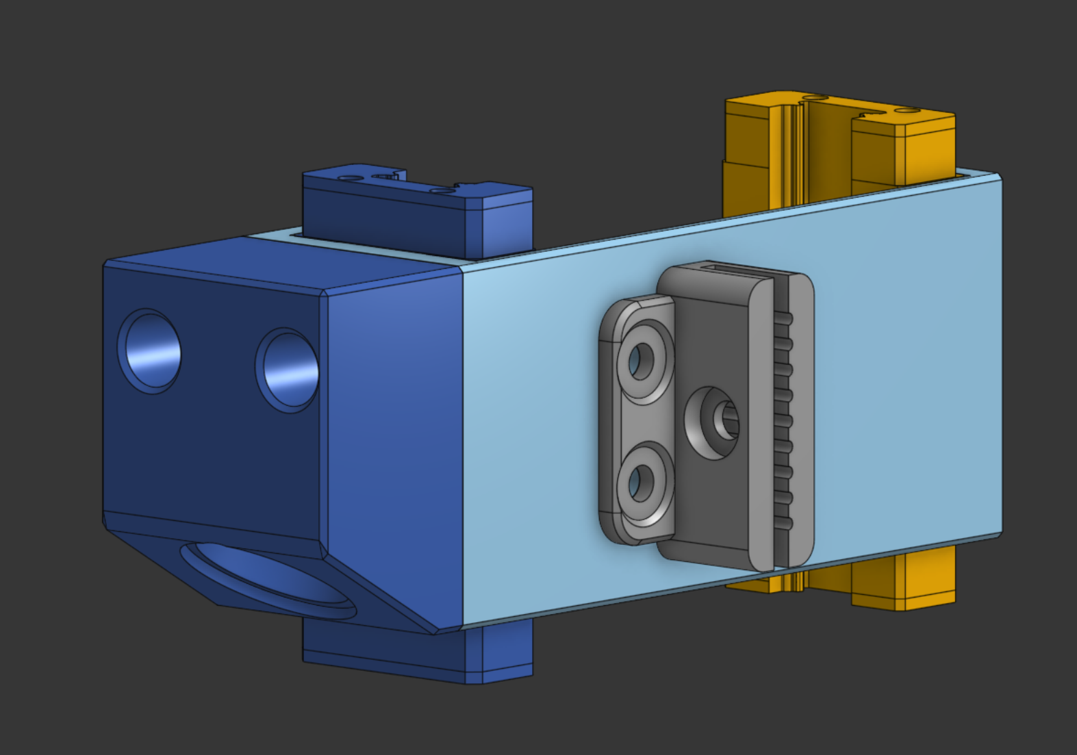
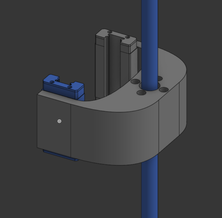
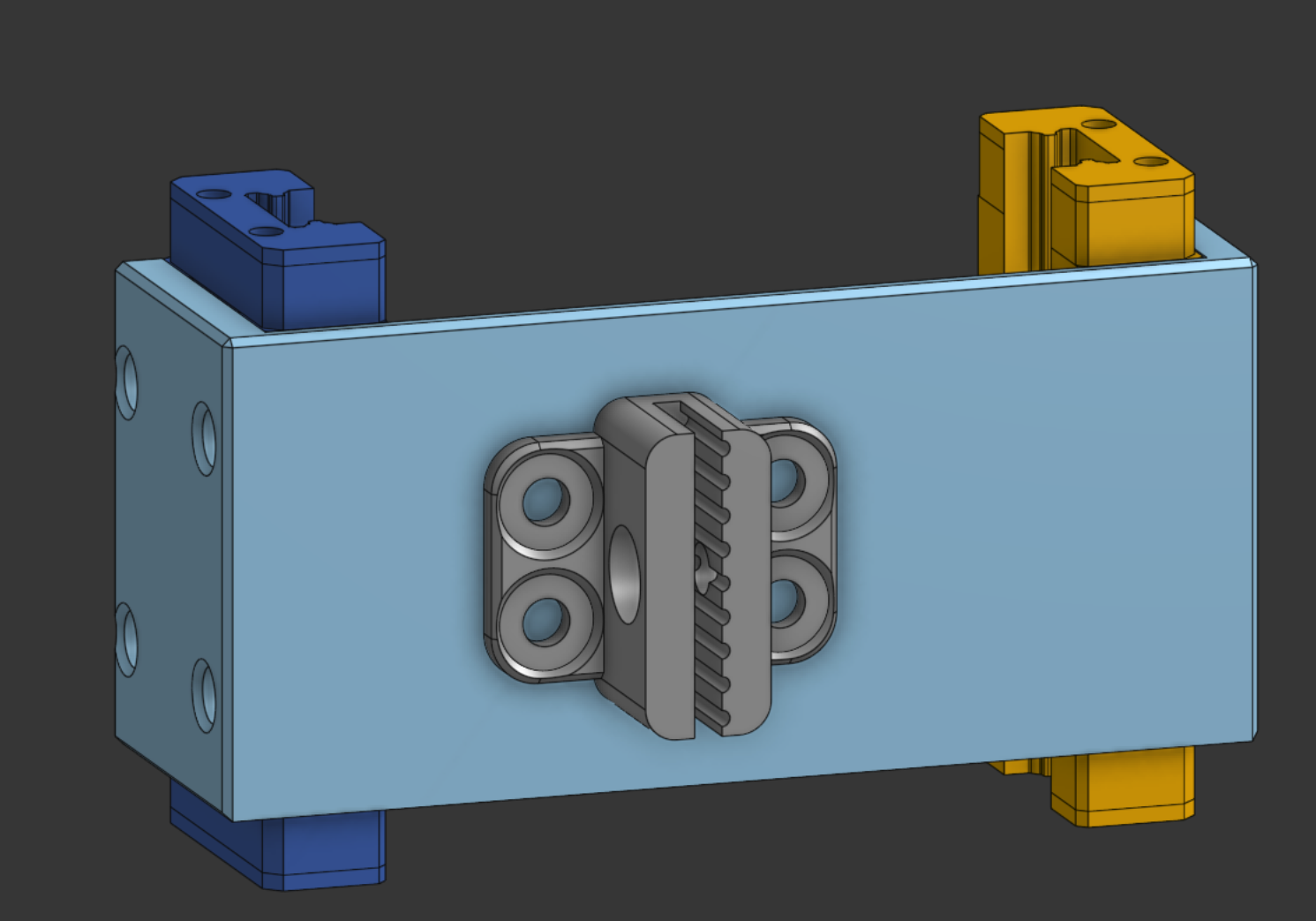
Here’s the new carrier. It holds a simple F695ZZ flanged bearing on the side. I’m going to also remove the secondary linear rail—just adding expense I don’t actually need.
The design also does this cool thing:
It’s a tnut slot :3
I have a TON of M6 tnuts, so I’m just going to use those in this thing instead of heat-set inserts or inserting square nuts. These hold well, and they’re quite strong too.
the final stretch
I’ve changed from the flanged F695ZZ bearings to simple 605rs bearings like a skateboard uses. All I need is spinny, so I’m getting a $10 50 pack from amazon.
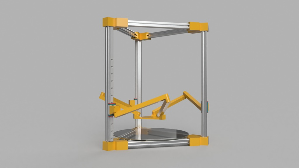
Here’s the final project:
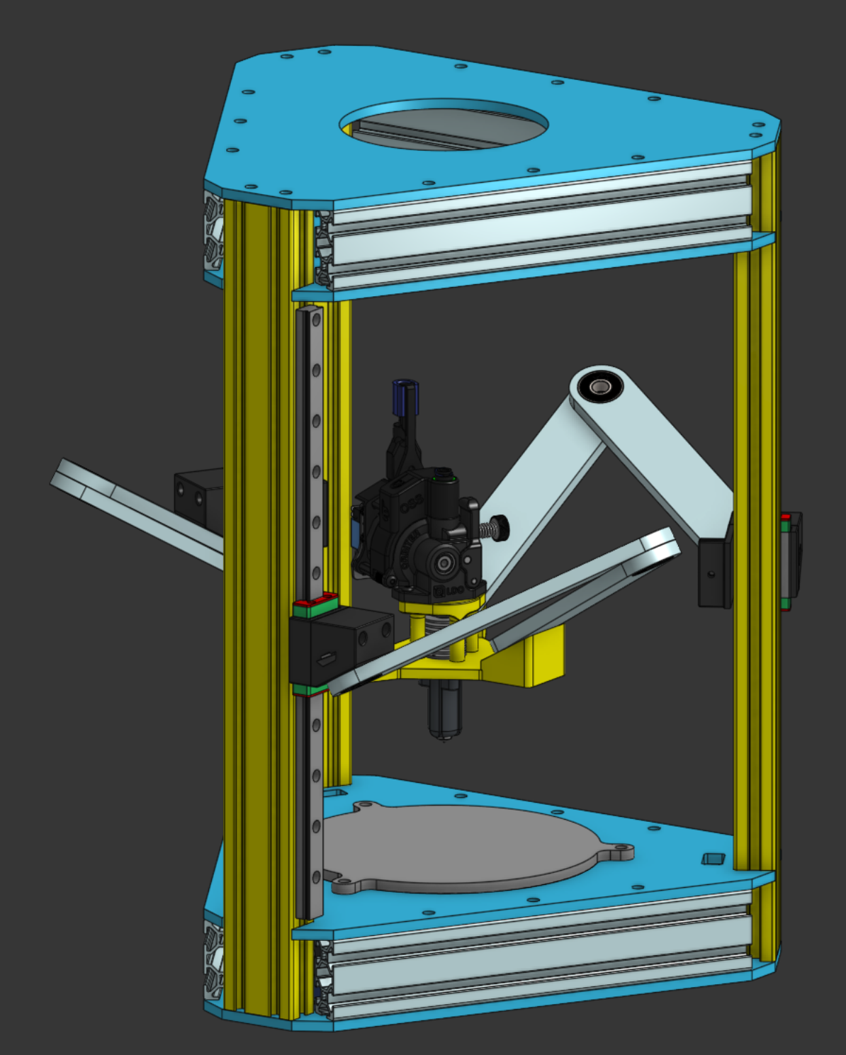
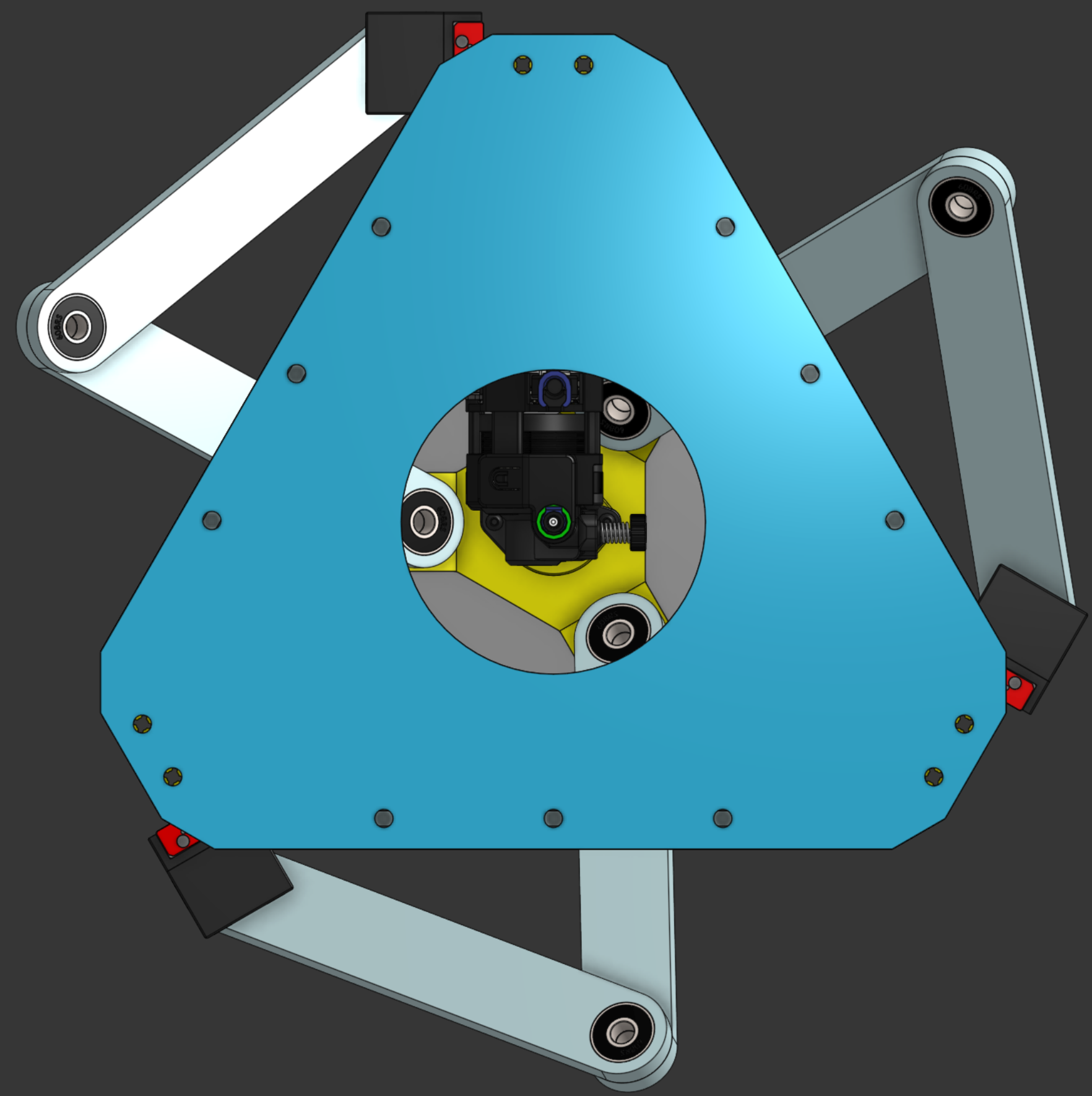
I’ve stylized it to look like David from Cyberpunk Edgerunners. I think I could do this a bit better, probably, but oh well lol.
The bed just screws onto the top plate with a few bolts, I’ll likely be machining this myself. The toolhead uses an orbiter 2.5 and lancer standard because I have those on hand and really like them, along with an Orbitool toolboard.