moron
Made by: @redbigz // may
Repository link: https://github.com/RedBigz/moron
Total hours so far: 48.5
- I have a 3D printer or will be getting one before March 21st
7/3
Mind Map
Approximate hours: 2
So there used to be an old mind-map here that uses cross-gantry kinematics because I abandoned my plan for a hybrid polar-CoreXY V0-style printer. I just found out it’s stupid easy to make a polar bed!
Lazy susans spin infinitely and are relatively cheap (https://www.aliexpress.com/item/1005007540027466.html), so i can just screw some mounts in and have a polar bed! Would still have to devise printed idlers and such though.
Here’s my new mind map!

22/3-23/3
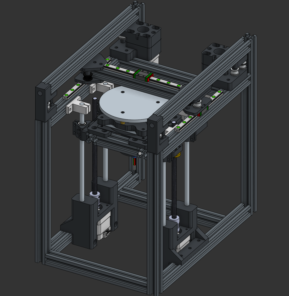
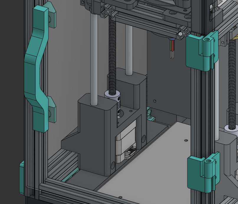
Z Axis
Approximate hours: 9
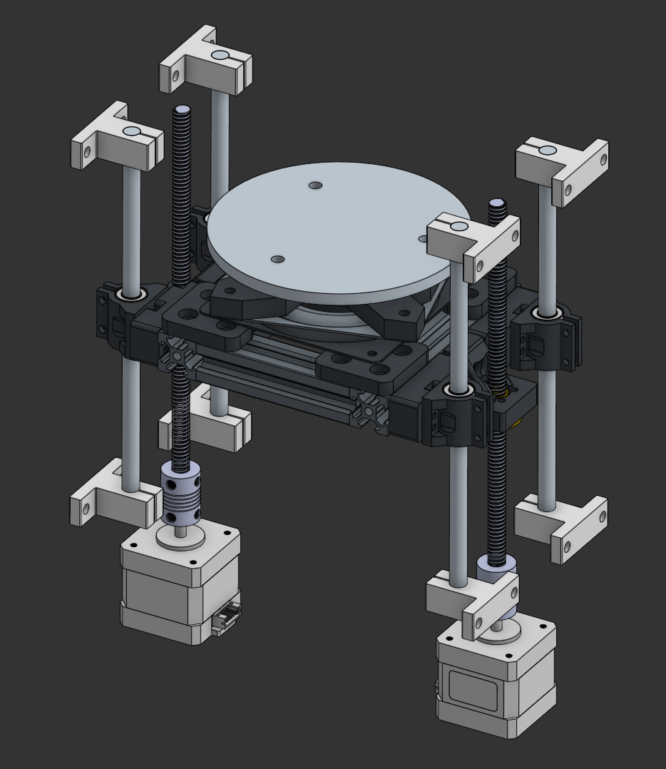
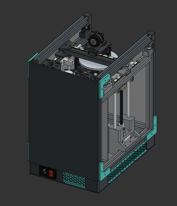
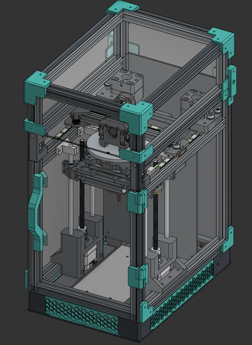
I created the Z axis, including the lazy susan system for the bed.
Bed
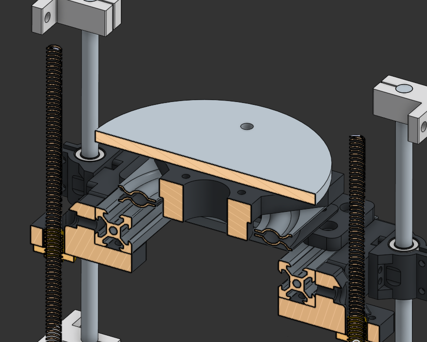
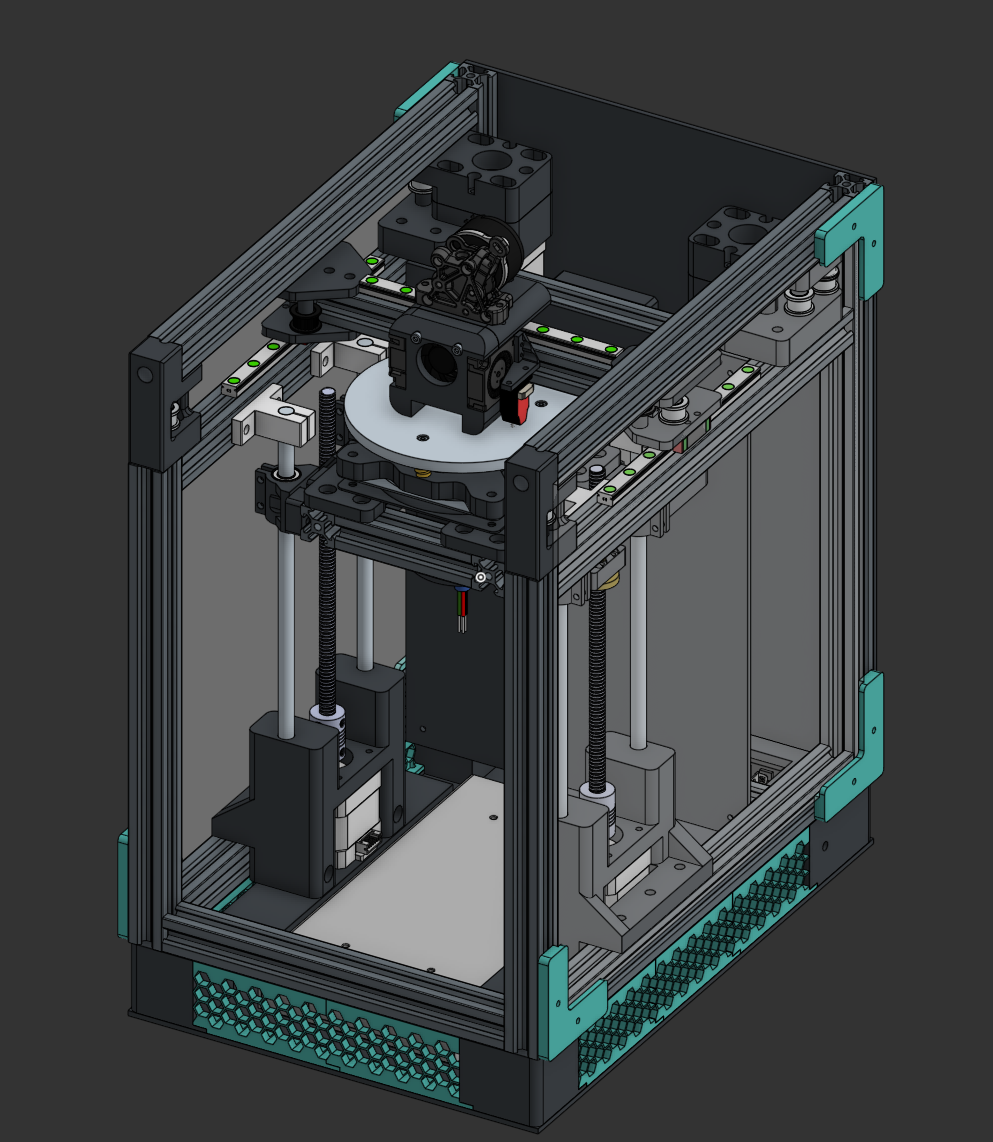
For the bed, I’m planning to CNC a custom 120mm diameter polar bed design (inspired by the V0 120mm plate). I mocked up a basic 6mm three-screw (M3) bedplate in OnShape and created all the necessary adapters to place it on the Z axis. A slip ring mount point was also implemented into the bed adapter to stop wire tangling. I’m using a 4” lazy susan for this as any larger would introduce more issues when mounting (I noticed >4” lazy susans have glued feet as well, which sucks).
Motion
I’m using two motors for the Z axis to maintain stability, as I couldn’t find a way to implement a cantilever polar bed since the weight requirements would be high.
I have yet to set up the polar rotation system, will do that soon.
That’s pretty much it <3
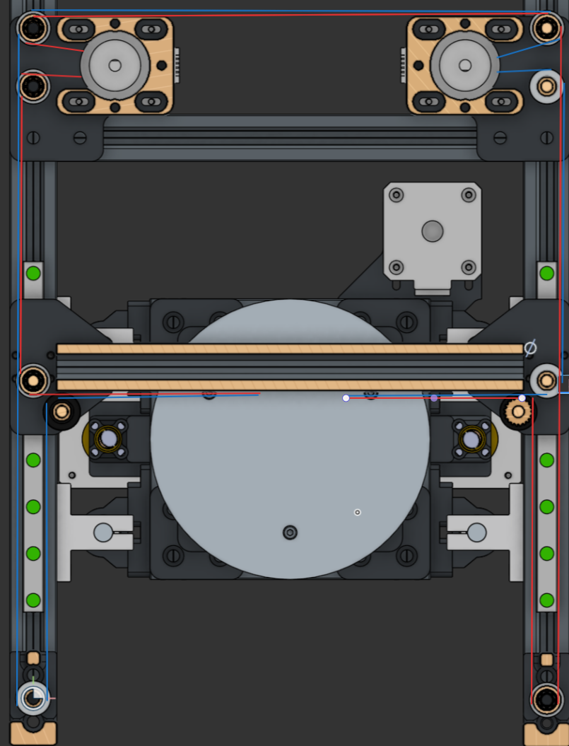
Rotation
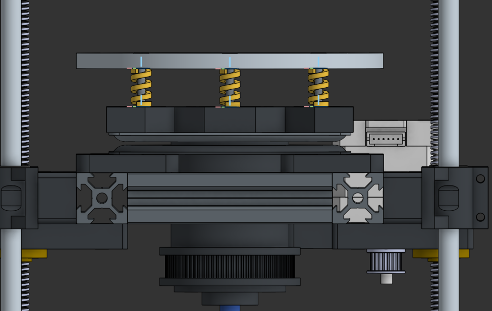
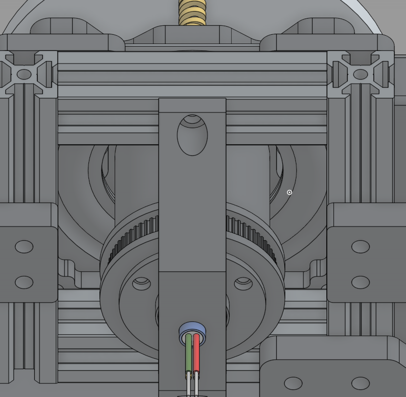
This took forever to set up. I realised that a belt path couldn’t be made above the lazy susan, so I elongated the slip ring and added 2GT teeth to allow for rotation under the bed.
24/3-26/3
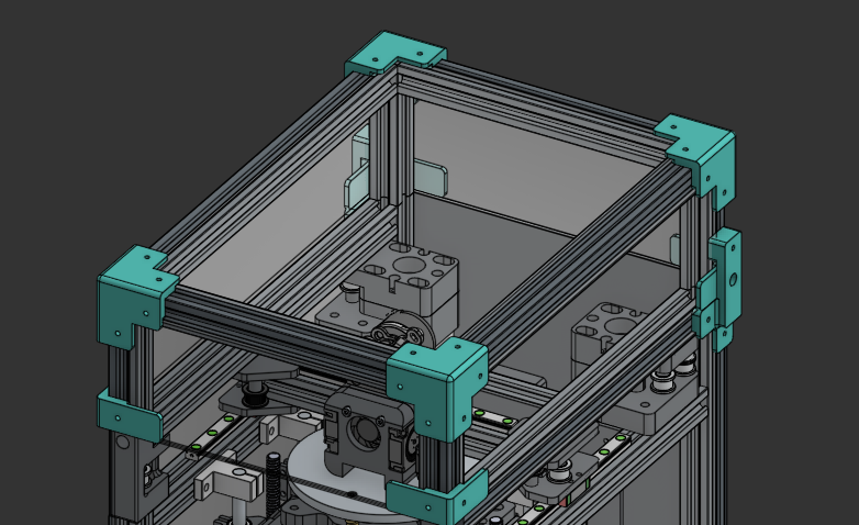
Gantry
Approximate hours: 9
I made the gantry! Yay! I ended up using MGN9 rails since linear rods would be annoying to tap, and they’re relatively cheap when you get them off sketchy AliExpress stores.
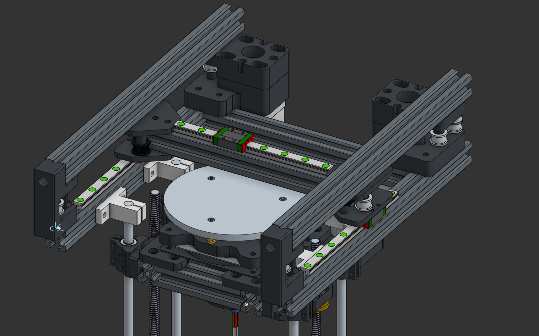
I ripped off the placement style of the idlers and motors from the Voron 0.2 since I barely had space, but all the modelling and calculations were done by me.
BEHOLD: THE CRAPPY EXCALIDRAW BELT PATH
26/3-28/3
Frame
Approximate hours: 1
this was pretty boring lmao
I haven’t done the top hat yet (seen in V0s — yeah I’m kind of making this really Vorony [Vorony, Voronic? Eh I dunno]), since that ties in with the bowden system and I want to work on that first.
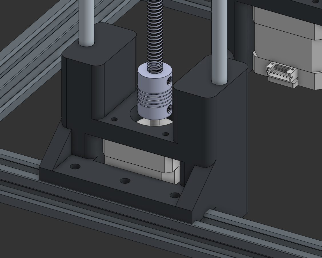
I had to redo the bottom smooth rod holders. I’m no longer using SK8A mounts on the bottom, in favour of a sturdy printed bracket I made. This was needed as the smooth rods were too short to mount to the bottom of the frame, meaning I would require more aluminium ($$$) to manufacture the printer. These holders also have the added benefit of securing the motors.
Toolhead
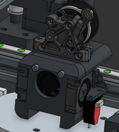
Approximate Hours: 7
i did itttttttt!
This toolhead took forever to make, but it’s so worth it! It’s running a V1 ProtoXtruder with a TZ E6 2.0 hotend, all in a Dragonburner-style shape! I’m in love <3
I ended up deciding to use two 3010 blowers for part cooling and a 3010 axial for the heatsink. I also tacked on a BiQu microprobe because an Eddy was too big lol
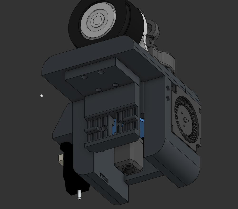
I’m using an MGN7H carriage for motion, and a simple belt clamp that’s parallel to the extrusion.
29/3
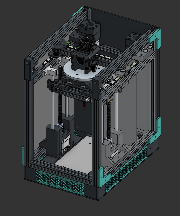
Exterior & Electronics
Approximate Hours: 8
hewwo!
this section is big so i’m splitting it into two sections:
Electronics
After talking with WilliamPrime on the Slack channel, I opted for a Mellow FLY D7 mobo! It’s super cheap and way smaller than an octopus, so it should work :3. I made a mount on the back for the Fly’s profile in hopes that it would mount. Better wait and see.
I made a mount for the PSU by modifying the motor mounts to allow for an attachment angle bracket to be screwed in. It’s a pretty dirty job, but I’m on a time constraint here.
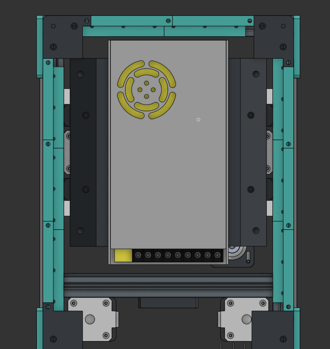
I also set up an IEC connector on a skirt that I’ll use to connect mains.
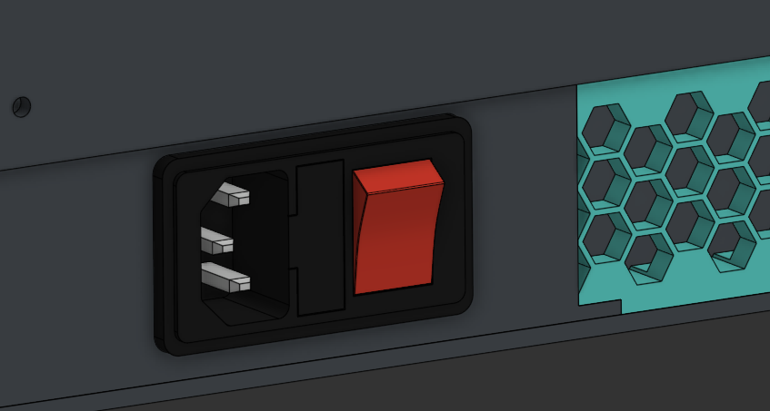
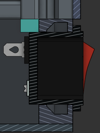
(snap fits ftw)
Exterior
I ended up making primitive corner clips to hold the side acrylic sheets in. I also determined the sizes for the ACM flute sheets for the interior of the printer. I have yet to make the top hat or the front hinge. I think I’ll go with a screw-in top hat since a hinge seems difficult to make and work with. I haven’t set up a model for the bottom sheet (above the PSU), as I may print that instead — due to the complicated shape.
Note from the future (31/3/26): I have swapped to using flute board from ACM! ACM’s just so expensive!
Additionally, I have added a bowden intake on the foot holding the IEC inlet, to allow for easy filament feeding.
30/03
Top Hat and Exterior
Approximate Hours: 6
I designed an extremely basic top hat to contain the filament Bowden tube. It’s nothing special. It’s connected via a basic clip that secures it with two M3 fasteners.
I also created a hinge system for the front panel, using 10x2mm magnets for the handle and basic screw-based hinges.
Small Fixes
Approximate Hours: 0.5
Slip Ring Reinforcement
I ended up reinforcing the rotor of the slip ring with a basic bracket, which should hold considering I won’t be spinning this bed that fast.
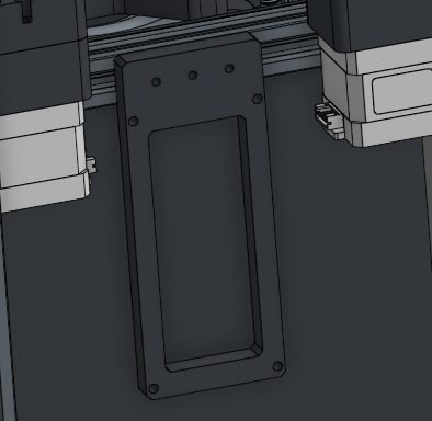
USB-C Outlet
In the previous log, I forgot to mention that I would need a USB-C outlet. As I don’t have an SBC at the moment, I’ve decided to use an old laptop or server instead. In that case, I would need a data port running to the exterior of the printer.
Here it is! I found a simple mount online and worked on the profiles. It should hold up well for now, at least.
31/03
BOM
Approximate Hours: 5
hewwo!
The BOM is pretty much complete! I had to substitute a LOT of items (such as the CNC bed) since everything’s soooo expensive :(. I arrived at an out-of-pocket value of about $40 excluding filament, which is about $59 AUD. Not bad! Check it out here.
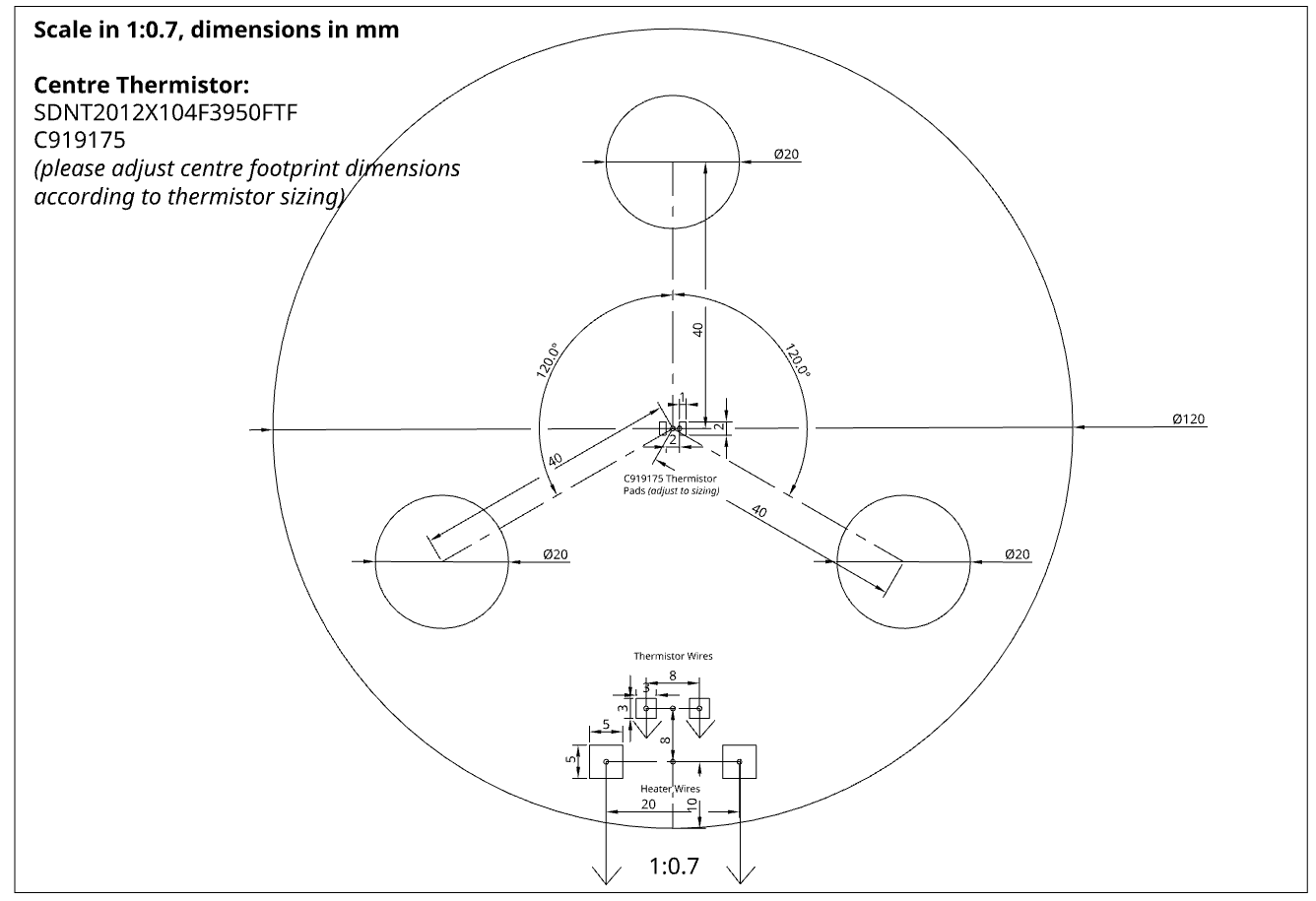
Cut Files & Flex Heater
Approximate Hours: 1
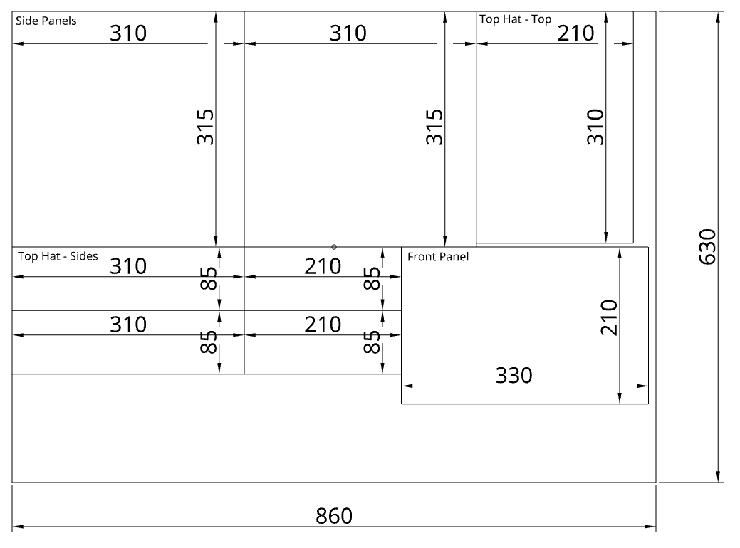
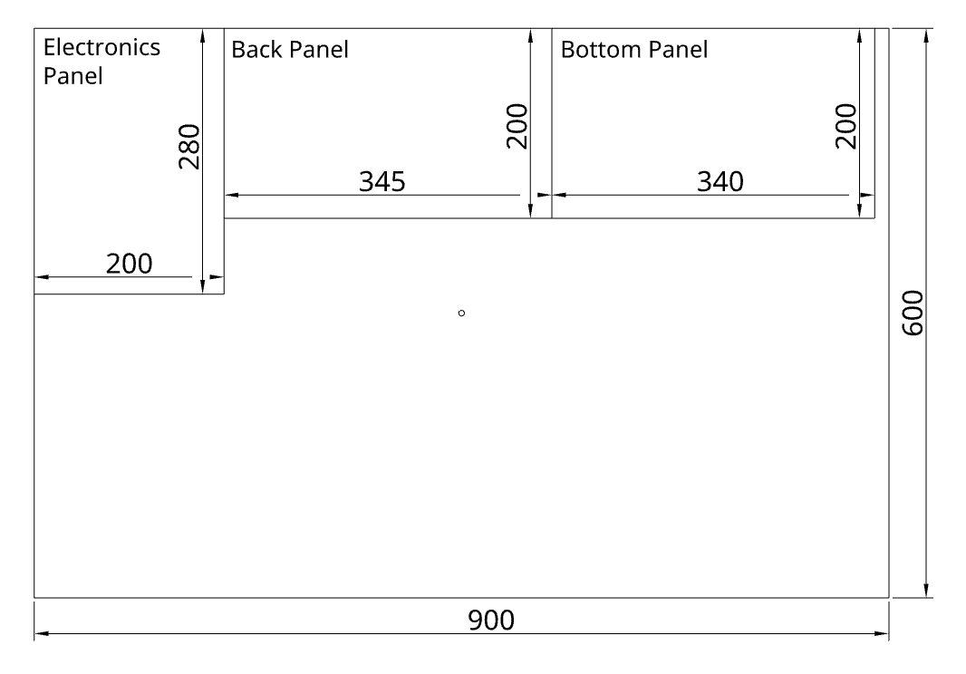
I made all the cut files for the acrylic and flute board! They’re published in the cad/cuts/ folder in the repo.
I also made the flex heater drawing! I’ll send it to JLC and they should be able to engineer traces out of it: